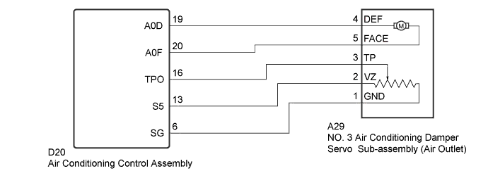
DTC B1438/49 Open in Air Outlet Damper Position Sensor Circuit |
DTC B1439/-49 Short in Air Outlet Damper Position Sensor Circuit |
DTC B1443/E49 Air Outlet Damper Control Servomotor Circuit |
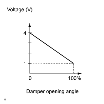
| DTC No. | DTC Detection Condition | Trouble Area |
| B1438/49 | Open in Air Outlet Damper Position Sensor Circuit |
|
| B1439/-49 | Short in Air Outlet Damper Position Sensor Circuit |
|
| B1443/43 | Air outlet damper Control servo motor circuit |
|
| 1.READ VALUE USING GTS |
Connect the GTS to the DLC3.
Turn the ignition switch to ON.
Turn the GTS on.
Operate the MODE switch.
Enter the following menus: Body Electrical / Air Conditioner / Data List.
Check the value(s) by referring to the table below.
| Tester Display | Measurement Item/Range | Normal Condition | Diagnostic Note |
| Air Outlet Damper Position | Air outlet damper position / Min.: -32.68%, Max.: 133.33% | FACE: -16.7% B/L: 10% FOOT-0: 50% (Manual operation) FOOT/DEF: 90% DEF: 116.7% | - |
| Air Outlet Damper Target | Air outlet damper target position / Min.: -32.68%, Max.: 133.33% | FACE: -16.7% B/L: 10% FOOT-0: 50% (Manual operation) FOOT/DEF: 90% DEF: 116.7% | - |
|
| ||||
| OK | |
 |
| 2.CHECK FOR DTC |
Clear the DTCs .
Check the DTCs .
|
| ||||
| OK | ||
 | ||
| ||
| 3.CHECK HARNESS AND CONNECTOR (NO. 3 AIR CONDITIONING RADIATOR DAMPER SERVO SUB-ASSEMBLY - AIR CONDITIONING CONTROL ASSEMBLY) |
Disconnect the D20 air conditioning control assembly.
Disconnect the A29 No. 3 air conditioning radiator damper servo sub-assembly (air outlet).
Measure the resistance according to the valve(s) in the table below.
| Test Connection | Condition | Specified Condition |
| A29-1(GND) - D20-6(SG) | Always | Below 1Ω |
| A29-2(VZ) - D20-13(S5) | Always | Below 1Ω |
| A29-3(TP) - D20-16(TPO) | Always | Below 1Ω |
| A29-4(DEF) - D20-19(A0D) | Always | Below 1Ω |
| A29-5(FACE) - D20-20A0F) | Always | Below 1Ω |
| A29-1(GND) - Body ground | Always | 10 kΩ or higher |
| A29-2(VZ) - Body ground | Always | 10 kΩ or higher |
| A29-3(TP) - Body ground | Always | 10 kΩ or higher |
| A29-4(DEF) - Body ground | Always | 10 kΩ or higher |
| A29-5(FACE) - Body ground | Always | 10 kΩ or higher |
|
| ||||
| OK | |
|
| 4.INSPECT NO. 3 AIR CONDITIONING RADIATOR DAMPER SERVO SUB-ASSEMBLY |
Remove the No. 3 air conditioning radiator damper servo sub-assembly (air outlet) .
Potentiometer circuit inspection
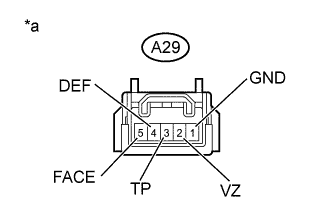 |
Measure the resistance according to the value(s) in the table below.
| Tester Connection | Condition | Specified Condition |
| A29-1(GND) - A29-2(VZ) | Always | 4.2 to 7.8 kΩ |
| *a | Component without harness connected (No. 3 air conditioning radiator damper servo sub-assembly) |
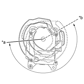 |
Measure the resistance according to the value(s) in the table below.
| Tester Connection | Condition | Specified Condition |
| A29-1(GND) - A29-3(TP) | FACE position | 3.4 to 6.2 kΩ |
| A29-1(GND) - A29-3(TP) | DEF position | 0.8 to 1.6 kΩ |
| *a | FACE |
| *b | DEF |
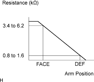 |
As the arm of the No. 3 air conditioning radiator damper servo motor moves from the FACE side to the DEF side, the resistance decreases gradually without interruption.
Motor circuit inspection
When the terminal 5 (FACE) of the connector A29 is connected to the battery positive terminal, and terminal 4 (DEF) of the connector A29 is connected to the battery negative terminal, confirm that the arm smoothly rotates from DEF to FACE.
When the terminal 4 (DEF) of the connector A29 is connected to the battery positive terminal, and terminal 5 (FACE) of the connector A29 is connected to the battery negative terminal, confirm that the arm smoothly rotates from FACE to DEF.
|
| ||||
| OK | ||
| ||
| ||

