CYLINDER HEAD > REPLACEMENT |
| 1. REPLACE NO. 2 INTAKE VALVE GUIDE BUSH |
Place the cylinder block on wooden blocks with the combustion chamber side facing upward.
![]() |
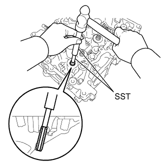
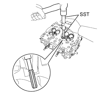
Using SST and a hammer, tap out the No. 2 intake valve guide bush.
Before installing the No. 2 intake valve guide bush, make sure that neither scratches nor damages exist on the inner surface of cylinder head valve guide bush holes.
![]() |
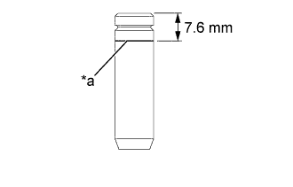
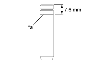
Draw a reference line 7.6 mm (0.299 in.) below from the top face on a new No. 2 intake valve guide bush using a marker.
| *a | Reference line |
Place the cylinder block on wooden blocks with the combustion chamber side facing downward.
Apply enough engine oil to the No. 2 intake valve guide bush, and set it on the cylinder head.
![]() |
Using SST and a hammer, tap in the No. 2 intake valve guide bush to the reference line.
![]() |
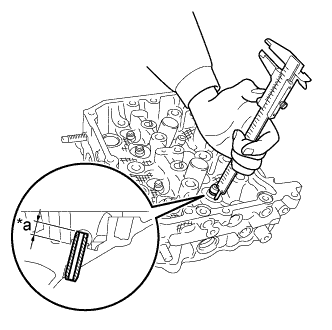
While measuring the No. 2 intake valve guide bush protrusion amount using a vernier caliper, tap in the No. 2 intake valve guide bush so that its height is within the standard.
| *a | Protrusion height |
Place the cylinder block on wooden blocks with the combustion chamber side facing upward.
![]() |
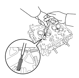
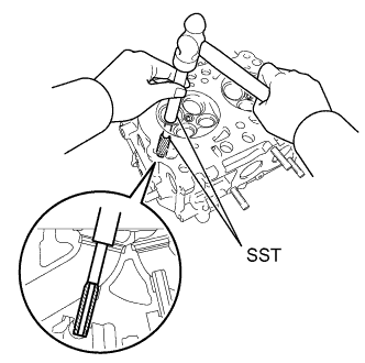
Using a reamer, ream the No. 2 intake valve guide bush to obtain the standard clearance between the No. 2 intake valve guide bush and valve stem.
After reaming, remove chips and clean the No. 2 intake valve guide bush.
Measure the inside diameter of the No. 2 intake valve guide bush and confirm the oil clearance.
Check the contact condition between the valve and valve seat.
| 2. REPLACE NO. 2 EXHAUST VALVE GUIDE BUSH |
Place the cylinder block on wooden blocks with the combustion chamber side facing upward.
![]() |
Using SST and a hammer, tap out the No. 2 exhaust valve guide bush.
Before installing the No. 2 exhaust valve guide bush, make sure that neither scratches nor damages exist on the inner surface of cylinder head valve guide bush holes.
![]() |
Draw a reference line 7.6 mm (0.299 in.) below from the top face on a new No. 2 exhaust valve guide bush using a marker.
| *a | Reference line |
Place the cylinder block on wooden blocks with the combustion chamber side facing downward.
Apply enough engine oil to the No. 2 exhaust valve guide bush, and set it on the cylinder head.
![]() |
Using SST and a hammer, tap in the No. 2 exhaust valve guide bush to the reference line.
![]() |
While measuring the No. 2 exhaust valve guide bush protrusion amount using a vernier caliper, tap in the No. 2 exhaust valve guide bush so that its height is within the standard.
| *a | Protrusion height |
Place the cylinder block on wooden blocks with the combustion chamber side facing upward.
![]() |
Using a reamer, ream the No. 2 exhaust valve guide bush to obtain the standard clearance between the No. 2 exhaust valve guide bush and valve stem.
After reaming, remove chips and clean the No. 2 exhaust valve guide bush.
Measure the inside diameter of the No. 2 exhaust valve guide bush and confirm the oil clearance.
Check the contact condition between the valve and valve seat.