CYLINDER BLOCK > REASSEMBLY |
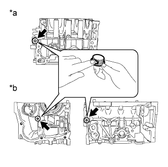
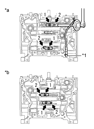
| 1. INSTALL NO. 1 CYLINDER BLOCK TIGHT PLUG |
|
| *a | for Bank 1 |
| *b | for Bank 2 |
Apply seal packing to the threaded portion of the No. 1 cylinder block tight plugs and install them to the cylinder block (for bank 1) and cylinder block (for bank 2).
| 2. INSTALL CRANKSHAFT SENSOR HOLDER ASSEMBLY |
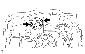 |
Install the crankshaft sensor holder assembly to the cylinder block (for bank 2) with the 2 bolts.
| 3. INSTALL CYLINDER BLOCK PLATE |
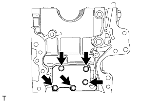 |
Install the cylinder block plate to the cylinder block (for bank 2) with the 5 bolts.
| 4. INSTALL OIL SEPARATOR COVER |
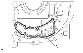 |
Using a sealer gun, apply seal packing in a continuous line as shown in the illustration.
| *a | φ3.5 to 5.0 mm (0.138 to 0.197 in.) |
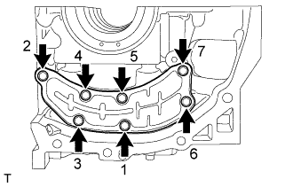 |
Tight the 7 bolts in the order shown in the illustration to install the oil separator cover to the cylinder block (for bank 1).
| 5. INSTALL O-RING |
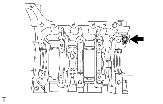 |
Attach a new O-ring to the cylinder block (for bank 2).
| 6. INSTALL CRANKSHAFT BEARING |
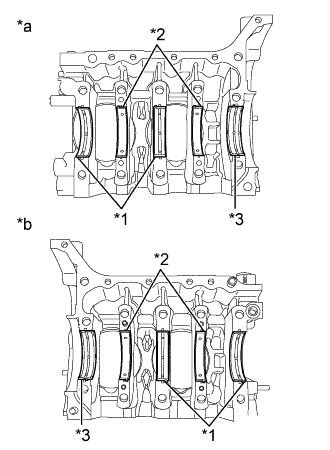 |
Apply engine oil to the crankshaft bearing, and install them to the cylinder block (for bank 1) and cylinder block (for bank 2).
| *1 | No. 1 and No. 3 Bearings (with groove) |
| *2 | No. 2 and No. 4 Bearings (without groove) |
| *3 | No. 5 Bearing |
| *a | for Bank 1 |
| *b | for Bank 2 |
| 7. INSTALL CRANKSHAFT |
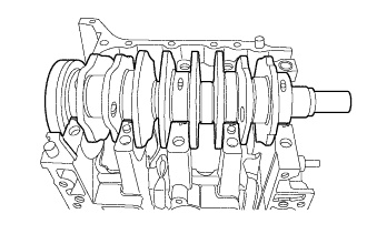 |
Apply engine oil to the crankshaft journals and place the crankshaft on the cylinder block (for bank 2).
| 8. INSTALL CYLINDER BLOCK SUB-ASSEMBLY (for Bank 1) |
Using a sealer gun, apply seal packing to the mating surface of the cylinder block sub-assembly (for bank 1) as shown in the illustration.
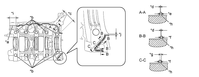
| *a | φ3.5 to 4.5 mm (0.138 to 0.177 in.) | *b | φ0.5to 1.5 mm (0.0197 to 0.0591 in.) |
| *c | Range of A-A | *d | Within φ1.0 mm (0.039 in.) |
| *e | φ2.7 to 3.7 mm (0.106 to 0.146 in.) | *f | φ3.5 to 4.5 mm (0.138 to 0.177 in.) |
| *g | φ2.0 mm (0.079 in.) | *h | Chamfer edge |
| *i | 36.0 mm (1.417 in.) | *j | 2.5 mm (0.098 in.) |
Place the cylinder block sub-assembly (for bank 1) to the cylinder block sub-assembly (for bank 2).
Apply engine oil to the washers and cylinder block bolt threads.
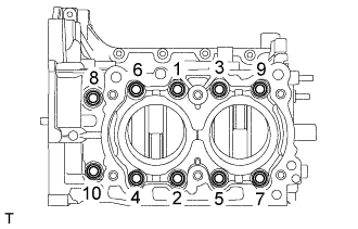 |
Using a 12 mm socket wrench, tighten the 10 bolts in the order shown in the illustration.
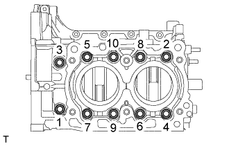 |
Using a 12 mm socket wrench, loosen the 10 bolts by 180 ° in the order shown in the illustration.
|
Using a 12 mm socket wrench, tighten the 10 bolts in the order shown in the illustration.
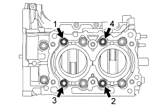 |
Using a 12 mm socket wrench, loosen the 4 bolts by 180 ° in the order shown in the illustration.
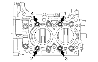 |
Using a 12 mm socket wrench, tighten the 4 bolts in the order shown in the illustration.
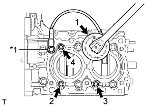 |
Using a 12 mm socket wrench and an angle gauge, tighten the 4 bolts by additional 60° in the order shown in the illustration.
| *1 | Temporary Bolt |
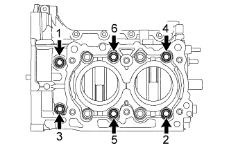 |
Using a 12 mm socket wrench, loosen the 6 bolts by 180 ° in the order shown in the illustration.
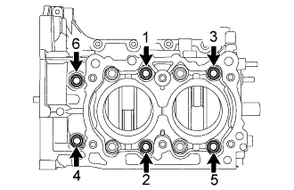 |
Using a 12 mm socket wrench, tighten the 6 bolts in the order shown in the illustration.
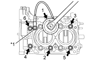 |
Using a 12 mm socket wrench and an angle gauge, tighten the 6 bolts by additional 60° in the order shown in the illustration.
| *1 | Temporary Bolt |
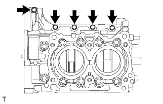 |
Tighten the 5 bolts.
| 9. INSTALL REAR ENGINE OIL SEAL |
Apply a light coat of engine oil to a new rear engine oil seal inner periphery and outer periphery.
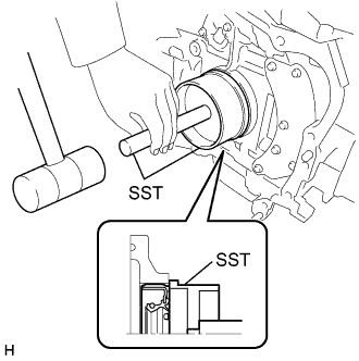 |
Using SST and a hammer, tap in the rear engine oil seal uniformly to the position shown in the illustration.
| 10. INSTALL CYLINDER BLOCK SUB-ASSEMBLY |
Mount the cylinder block sub-assembly onto an engine stand.
| 11. INSTALL PISTON WITH PIN SUB-ASSEMBLY |
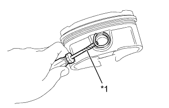 |
Using a screwdriver with its tip wrapped in protective tape, install the piston pin hole snap ring on one end of the piston.
| *1 | Protective Tape |
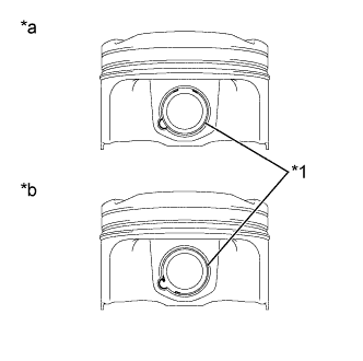 |
| *1 | Piston Pin Hole Snap Ring |
| *a | Correct |
| *b | Incorrect |
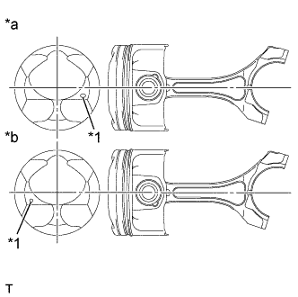 |
Set the piston to the connecting rod.
| *1 | Front Mark |
| *a | for Bank 1 |
| *b | for Bank 2 |
Apply engine oil to the piston pin and install it to the piston.
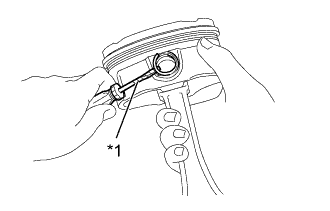 |
Using a screwdriver with its tip wrapped in protective tape, install the piston pin hole snap ring to the piston.
| *1 | Protective Tape |
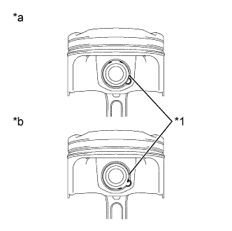 |
| *1 | Piston Pin Hole Snap Ring |
| *a | Correct |
| *b | Incorrect |
| 12. INSTALL PISTON RING SET |
Install the oil ring expander, lower oil ring side rail and upper oil ring side rail in order by hand.
Set the oil ring expander ends at the location B in the illustration.
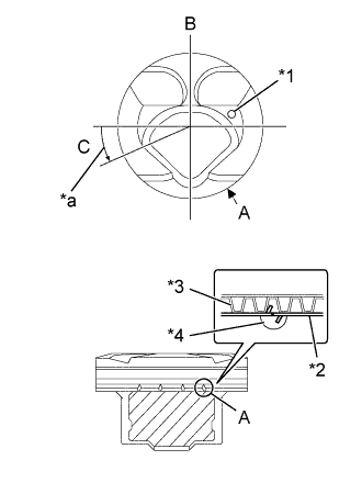 |
Hook the stoppers at the rail ends of the lower oil ring side rail into cutout A of the piston and the oil ring expander as shown in the illustration.
Align the rail ends of the upper oil ring side rail within the range C and hook the stopper into the oil ring expander.
Using a piston ring expander, install the No. 2 compression ring and No. 1 compression ring in order.
| *1 | Front Mark |
| *2 | Lower Oil Ring Side Rail |
| *3 | Expander |
| *4 | Cutout |
| *a | 0 to 20° |
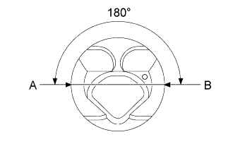 |
Set the No. 1 compression ring ends at the location A or B in the illustration.
Set the No. 2 compression ring ends at the location A or B, that is 180° opposite of those of the No. 1 compression ring.
Check that the piston rings and oil rings are correctly set.
| 13. INSTALL PISTON SUB-ASSEMBLY WITH CONNECTING ROD |
Operate the engine stand so that the oil pan side faces upward.
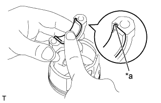 |
Install the connecting rod bearings to the connecting rod and connecting rod cap. <*1>
| *a | Claw |
Check that the piston rings and oil rings are correctly set.
Apply engine oil to the piston and inside the cylinder bore.
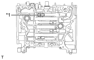 |
Turn the crankshaft so that the crank pin is positioned at TDC.
| *1 | Crank Pin |
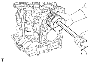 |
Using a piston ring compressor, compress the piston rings and insert the piston with connecting rod into the cylinder block.
Apply engine oil to the seating face of the connecting rod cap and threads of the connecting rod cap bolts.
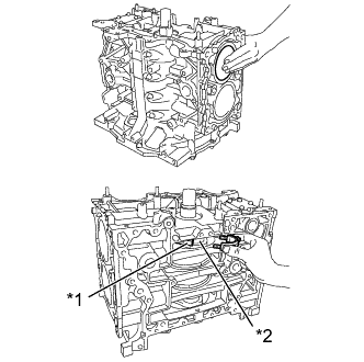 |
While pushing the piston top, turn the crankshaft to position the crankshaft pin and connecting rod large end as shown in the illustration, and then attach the connecting rod cup with 2 new connecting rod cap bolts.
| *1 | Connecting Rod |
| *2 | Crankshaft Pin |
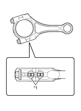 |
| *1 | Matching Symbol |
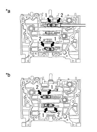 |
Using a "TORX" socket wrench E14, tighten the 2 connecting rod cup bolts in the order shown in the illustration.
| *a | No. 1 and No. 4 |
| *b | No. 2 and No. 3 |
Retighten the 2 connecting rod cup bolts in the same order as above. <*2>
In the same procedures from <*1> to <*2>, install the No. 2, No. 3 and No. 4 piston with connecting rods.
 |
Using a "TORX" socket wrench E14 and an angle gauge, tighten the connecting rod cup bolts for the No. 1 to No. 4 piston with connecting rods by additional 92.5°.
| *1 | Temporary Bolt |
| *a | No. 1 and No. 4 |
| *b | No. 2 and No. 3 |
Check that the crankshaft can be turned smoothly.