 |
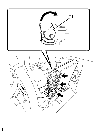
Connect the 4 connectors to the injector driver. Move the lock levers in the direction indicated by the arrow to lock the 3 connectors.
| *1 | Lock Lever |
 | Lock with Connector |
 | Normal Connector |
INTAKE MANIFOLD > INSTALLATION |
| 1. INSTALL INTAKE MANIFOLD |
Install the 2 new gaskets to the intake manifold.
Install the intake manifold with the 6 bolts.
Engage the 2 clamps and 4 connectors, and connect the wire harness.
Connect the fuel pump connector.
Engage the clamp and connect the engine wire harness.
Engage the 5 clamps and connect the battery cable.
Connect the purge valve connector.
Connect the manifold absolute pressure sensor connector.
| 2. CONNECT VENTILATION HOSE |
Connect the ventilation hose.
| 3. CONNECT VACUUM TUBE CONNECTOR HOSE (for Manual Transmission) |
Connect the vacuum tube connector hose with the bolt.
Connect the vacuum tube connector hose.
| 4. INSTALL NO. 1 ENGINE COVER SUB-ASSEMBLY (w/ Air Conditioning System) |
Engage the 3 claws and install the No. 1 engine cover sub-assembly.
| 5. CONNECT FUEL DELIVERY PIPE SUB-ASSEMBLY |
Connect the No. 2 fuel vapor feed hose.
Install the bolt and connect the fuel delivery pipe sub-assembly.
| 6. CONNECT NO. 1 FUEL HOSE (for Clamp Type) |
Connect the No. 1 fuel hose to the fuel delivery pipe with the clamp.
Tighten the hose clamp bolt.
| 7. CONNECT NO. 1 FUEL HOSE (for Metal Type) |
Connect the No. 1 fuel hose to the fuel delivery pipe (Click here).
| 8. INSTALL INJECTOR COVER (for Bank 2) |
Install the injector cover (for bank 2) to the intake manifold with the 2 bolts.
Install the wire harness clamp bracket to the injector cover (for bank 2) with the bolt.
| 9. INSTALL INJECTOR COVER (for Bank 1) |
Install the injector cover (for bank 1) to the intake manifold with the 2 bolts.
Engage the 4 clamps to install the wire harness to the injector cover (for bank 1).
| 10. INSTALL INJECTOR DRIVER |
Install the injector driver with the 3 bolts.
|
Connect the 4 connectors to the injector driver. Move the lock levers in the direction indicated by the arrow to lock the 3 connectors.
| *1 | Lock Lever |
| Lock with Connector |
| Normal Connector |
| 11. CONNECT THROTTLE WITH MOTOR BODY ASSEMBLY |
Install a new gasket to the intake manifold.
Install the throttle with motor body assembly to intake manifold with the 4 bolts.
| 12. INSTALL AIR CLEANER CAP WITH AIR CLEANER HOSE |
Install the air cleaner cap with air cleaner hose with the 3 blots.
Install the air cleaner cap with air cleaner hose with the 2 hose clamps.
Connect the No. 2 ventilation hose.
Connect the mass air flow meter connector.
Engage the wire harness clamp and install the wire harness to the air cleaner cap.
| 13. CONNECT CABLE TO NEGATIVE BATTERY TERMINAL |
| 14. INSPECT FUEL PUMP OPERATION AND INSPECT FOR FUEL LEAK |
Check fuel pressure.
Connect the GTS to the DLC3.
Start the engine.
Turn the GTS on.
Enter the following menus: Powertrain / Engine / Active Test / Control the Target Fuel Pressure.
Check that the fuel pressure fluctuates when the target fuel pressure changes.
Check operating sound.
Remove the injector cover (for bank 2).
Start the engine.
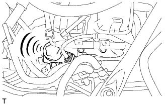 |
Using a sound scope, check the operating sound of the pump.
If no sound can be heard, check the fuel pump, wire harness and ECM.
Stop the engine.
Reinstall the injector cover (for bank 2).
| 15. INSPECT THROTTLE WITH MOTOR BODY ASSEMBLY |
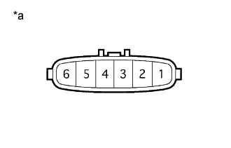 |
Measure the resistance according to the value(s) in the table below.
| *a | Component without harness connected (Throttle with Motor Body Assembly) |
| Tester Connection | Condition | Specified Condition |
| 1 - 2 | 20°C (68°F) | 0.3 to 100 Ω |