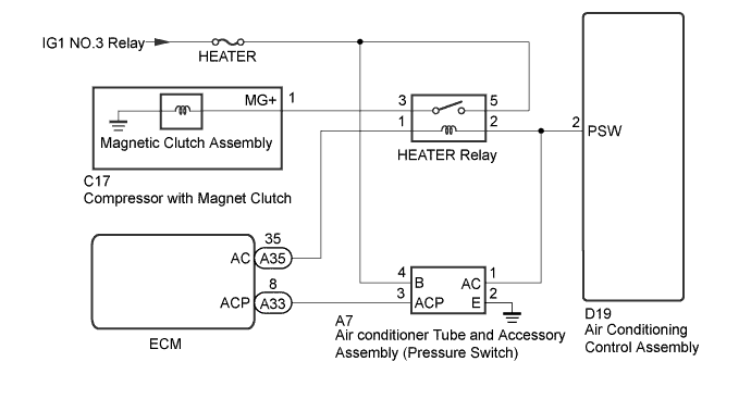
AIR CONDITIONING SYSTEM (for Automatic Air Conditioning System) > Air Conditioning Compressor Magnetic Clutch Circuit |
| 1.READ VALUE USING GTS |
Enter the following menus : Body Electrical / Air Conditioner / Date List.
Check the valve(s) by referring to the table below.
| Tester Display | Measurement Item/Range | Normal Condition | Diagnostic Note |
| Pressure Switch Operation (Pressure Switch Oper) | Pressure switch status / Normal or Abnormal | Normal | - |
| Result | Proceed to |
| NG | A |
| OK | B |
|
| ||||
| A | |
 |
| 2.CHECK REFRIGERANT VOLUME |
Check the refrigerant volume (for HFC-1234yf (R1234yf))
|
| ||||
| OK | |
|
| 3.CHECK HARNESS AND CONNECTOR (AIR CONDITIONER TUBE AND ACCESSORY ASSEMBLY - POWER SOURCE) |
Disconnect the A7 air conditioner tube and accessory assembly connector.
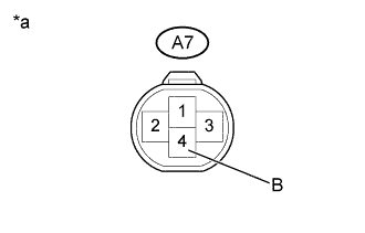 |
Measure the voltage according to the value(s) in the table below.
| Tester Connection | Condition | Specified Condition |
| A7-4(B) - Body ground | Ignition switch on | 11 to 14 V |
| *a | Front view of wire harness connector (to Air Conditioner Tube and Accessory Assembly) |
|
| ||||
| OK | |
|
| 4.CHECK HARNESS AND CONNECTOR (AIR CONDITIONER TUBE AND ACCESSORY ASSEMBLY - BODY GROUND) |
Measure the resistance according to the value(s) in the table below.
| Tester Connection | Condition | Specified Condition |
| A7-2(E) - Body ground | Always | Below 1 Ω |
|
| ||||
| OK | |
|
| 5.CHECK HARNESS AND CONNECTOR (AIR CONDITIONER TUBE AND ACCESSORY ASSEMBLY - ECM) |
Disconnect the A33 ECM connector.
Measure the resistance according to the value(s) in the table below.
| Tester Connection | Condition | Specified Condition |
| A7-3(ACP) - A33-8(ACP) | Always | Below 1 Ω |
| A7-3(ACP) - Body ground | Always | 10 kΩ or higher |
|
| ||||
| OK | |
|
| 6.CHECK HARNESS AND CONNECTOR (AIR CONDITIONER TUBE AND ACCESSORY ASSEMBLY - AIR CONDITIONING CONTROL ASSEMBLY) |
Disconnect the D19 air conditioning control assembly connector.
Measure the resistance according to the value(s) in the table below.
| Tester Connection | Condition | Specified Condition |
| A7-1(AC) - D19-2(PSW) | Always | Below 1 Ω |
| A7-1(AC) - Body ground | Always | 10 kΩ or higher |
|
| ||||
| OK | |
|
| 7.INSPECT AIR CONDITIONER TUBE AND ACCESSORY ASSEMBLY |
Inspect the air conditioner tube and accessory assembly
|
| ||||
| OK | ||
 | ||
| ||
| 8.READ VALUE USING GTS |
Connect the GTS to the DLC3.
Turn the ignition switch to ON.
Turn the GTS on.
Enter the following menus : Powertrain / Engine and ECT / Date List.
Check the value(s) by referring to the table below.
| Tester Display | Measurement Item/Range | Normal Condition | Diagnostic Note |
| A/C Signal | A/C switch status / ON or OFF | ON: A/C switch on OFF: A/C switch off | The air conditioning control assembly sends the A/C switch signal to the ECM via CAM communication |
| Result | Proceed to |
| NG | A |
| OK | B |
|
| ||||
| A | |
|
| 9.CHECK HARNESS AND CONNECTOR (HEATER RELAY - AIR CONDITIONING CONTROL ASSEMBLY) |
Remove the heater relay from the engine room relay block assembly.
Disconnect the D19 air conditioning control assembly connector.
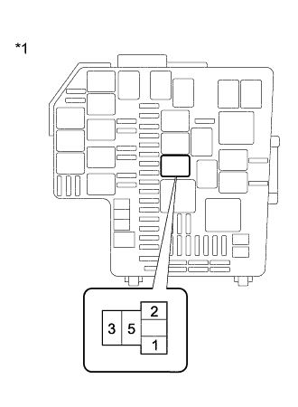 |
Measure the resistance according to the value(s) in the table below.
| Tester Connection | Condition | Specified Condition |
| 2 - D19-2(PSW) | Always | Below 1 Ω |
| 2 - Body ground | Always | 10 kΩ or higher |
| *1 | Engine room relay block assembly |
|
| ||||
| OK | |
|
| 10.CHECK HARNESS AND CONNECTOR (HEATER RELAY - ECM) |
Disconnect the A35 ECM connector.
|
Measure the resistance according to the value(s) in the table below.
| Tester Connection | Condition | Specified Condition |
| A35-35(AC) - 1 | Always | Below 1 Ω |
| A35-35(AC) - Body ground | Always | 10 kΩ or higher |
| *1 | Engine room relay block assembly |
|
| ||||
| OK | |
|
| 11.INSPECT RELAY (HEATER) |
Inspect the heater relay .
|
| ||||
| OK | |
|
| 12.CHECK HARNESS AND CONNECTOR (HEATER RELAY - POWER SOURCE) |
|
Measure the voltage according to the value(s) in the table below.
| Tester Connection | Condition | Specified Condition |
| 5 - Body ground | Ignition switch off | Below 1 V |
| Ignition switch on | 11 to 14 V |
| *1 | Engine room relay block assembly |
|
| ||||
| OK | |
|
| 13.CHECK HARNESS AND CONNECTOR (HEATER RELAY - COMPRESSOR WITH MAGNET CLUTCH) |
|
Disconnect the C17 compressor with magnet clutch connector.
Measure the valve(s) in the table below.
| Tester Connection | Condition | Specified Condition |
| C17-1(MG+) - 3 | Always | Below 1 Ω |
| C17-1(MG+) - Body ground | Always | 10 kΩ or higher |
| *1 | Engine room relay block assembly |
|
| ||||
| OK | |
|
| 14.INSPECT COMPRESSOR WITH MAGNET CLUTCH |
Inspect the compressor with magnet clutch .
|
| ||||
| OK | |
|
| 15.INSPECT AIR CONDITIONING CONTROL ASSEMBLY |
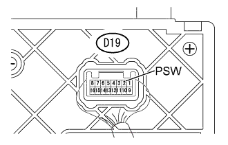 |
Measure the voltage according to the valve(s) in the table below.
| Tester Connection | Condition | Specified Condition |
| D19-2(PSW) - Body ground |
| 11 to 14 V |
| Below 1 V |
| *1 | Component with harness connected (Air Conditioning Control Assembly) |
|
| ||||
| OK | |
|
| 16.REPLACE ECM |
Replace the blower resistor with a new or normally functioning one
| NEXT | |
|
| 17.READ VALUE USING GTS |
Enter the following menus : Body Electrical / Air Conditioner / Date List.
Check the valve(s) by referring to the table below.
| Tester Display | Measurement item/Range | Normal Condition | Diagnostic Note |
| Pressure Switch Operation (Pressure Switch Oper) | Pressure switch status / Normal or Abnormal | Normal | - |
|
| ||||
| OK | ||
| ||
| ||

