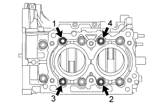
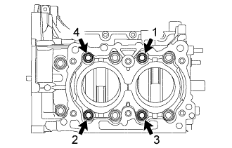
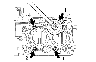
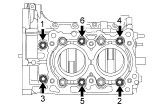
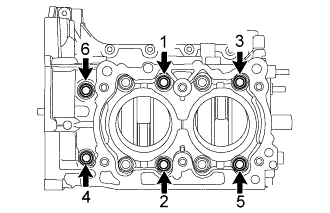
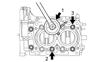
CYLINDER BLOCK > INSPECTION |
| 1. INSPECT CYLINDER BLOCK SUB-ASSEMBLY |
Visually check that there are no cracks, scratches or other damage.
Using a dye penetrant, check the important sections for fissures.
Check that there are no signs of gas leak or water leak on gasket attachment surfaces.
Check the oil passages for clogging.
| 2. INSPECT CYLINDER BLOCK FOR WARPAGE |
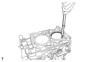
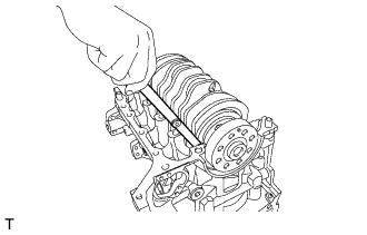
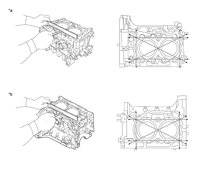
Using a precision straightedge and a feeler gauge, measure the surfaces that contact the cylinder head for warpage.

| *a | for Bank 1 | *b | for Bank 2 |
| 3. INSPECT CYLINDER BORE |
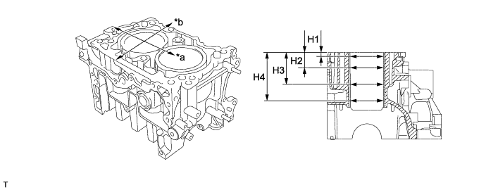
Using a cylinder gauge, measure the cylinder bore diameter at positions shown in the illustration and check for taper and out-of-round.

| *a | Piston pin direction | *b | Thrust direction |
| Cylinder bore size A | 86.005 to 86.015 mm (3.38602 to 3.38641 in.) |
| Cylinder bore size B | 85.995 to 86.005 mm (3.38562 to 3.38602 in.) |
| Taper | 0.030 mm (0.00118 in.) |
| Out-of-runout | 0.030 mm (0.00118 in.) |
| H1 | 10.0 mm (0.394 in.) |
| H2 | 45.0 mm (1.772 in.) |
| H3 | 80.0 mm (3.150 in.) |
| H4 | 105.0 mm (4.134 in.) |
![]() |
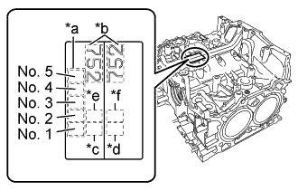
| *a | Main journal size mark |
| *b | Cylinder block (for bank 1 / for bank 2) combination mark |
| *c | No. 1 cylinder bore size mark |
| *d | No. 2 cylinder bore size mark |
| *e | No. 3 cylinder bore size mark |
| *f | No. 4 cylinder bore size mark |
| 4. INSPECT PISTON DIAMETER |
![]() |
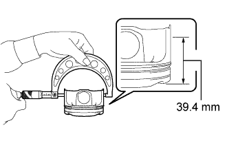
Using a micrometer, measure the piston diameter at right angles to the piston pin hole, and at a point 39.4 mm (1.551 in.) from the top of the piston head.
| A grade | 85.985 to 85.995 mm (3.38523 to 3.38562 in.) |
| B grade | 85.975 to 85.985 mm (3.38484 to 3.38523 in.) |
| 0.25 mm (0.0098 in.) over size | 86.225 to 86.245 mm (3.39468 to 3.39547 in.) |
| 0.50 mm (0.0197 in.) over size | 86.475 to 86.495 mm (3.40452 to 3.40531 in.) |
| 5. INSPECT PISTON OIL CLEARANCE |
Subtract the piston diameter measurement from the cylinder bore diameter measurement.
| 6. REPAIR CYLINDER LINER |
If any of the inside diameter, taper, out-of-round or piston oil clearance is out of standard, or if there is any damage on the cylinder liner, rebore it to replace with an oversized piston.
| 7. INSPECT PISTON WITH PIN |
Check the piston and piston pin for wear or cracks.
Check the piston pin hole snap ring for distortion or wear.
Check the piston ring groove for damage.
![]() |
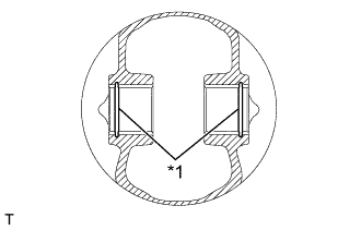
Check the piston pin hole snap ring groove for burr.
| *1 | Piston Pin Hole Snap Ring Groove |
Check if the piston pin can be pushed into the piston pin hole with your thumb.
| 8. INSPECT CONNECTING ROD SMALL END BUSH |
Check the bushing at connecting rod small end bush for damage.
| 9. INSPECT PISTON PIN OIL CLEARANCE |
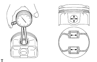
![]() |
Using a caliper gauge, measure the inside diameter of the piston pin hole.
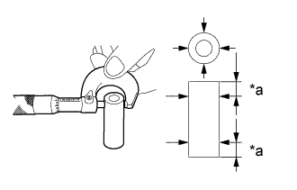
![]() |
Using a micrometer, measure the outer diameter of the piston pin.
| *a | 10.0 mm (0.394 in.) |
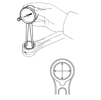
![]() |
Using a caliper gauge, measure the inside diameter of bushing at connecting rod small end.
Calculate the clearance between the piston pin hole and piston pin.
Calculate the clearance between piston pin and bushing at connecting rod small end.
| 10. INSPECT PISTON RING |
Make sure that the piston ring is not broken or damaged.
If the piston ring is broken or damaged, replace it with a new one.
| 11. INSPECT PISTON RING END GAP |
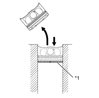
![]() |
Using a piston, push the piston ring into the cylinder.
| *1 | Piston ring |
![]() |
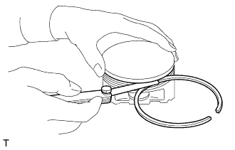
Using a feeler gauge, measure the end gap.
| No. 1 | 0.25 to 0.30 mm (0.00984 to 0.01181 in.) |
| No. 2 | 0.60 to 0.70 mm (0.02362 to 0.02756 in.) |
| Oil ring | 0.10 to 0.35 mm (0.00394 to 0.01378 in.) |
| 12. INSPECT RING GROOVE CLEARANCE |
![]() |
Using a feeler gauge, measure the clearance between the piston ring and the wall of the ring groove.
| No. 1 | 0.030 to 0.080 mm (0.00118 to 0.00315 in.) |
| No. 2 | 0.030 to 0.070 mm (0.00118 to 0.00276 in.) |
| 13. INSPECT CONNECTING ROD ASSEMBLY |
Check that the large or small end thrust surface is not damaged.
Check the connecting rod assembly bearing for scar, peeling, seizure, melting or wear, etc.
![]() |
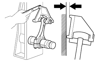
Using a rod aligner and feeler gauge, check the connecting rod assembly for bend.
![]() |
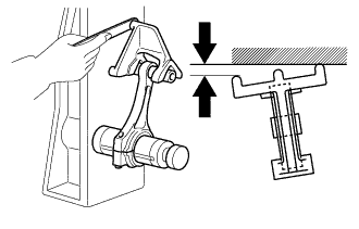
Using a rod aligner and feeler gauge, check the connecting rod assembly for twist.
| 14. INSPECT CONNECTING ROD THRUST CLEARANCE |
Clean the connecting rod bearings and crank pins, and apply engine oil to the crank pins. <*1>
![]() |
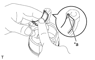
Align the claw and attach the connecting rod bearing to the connecting rod.
| *a | Claw |
![]() |
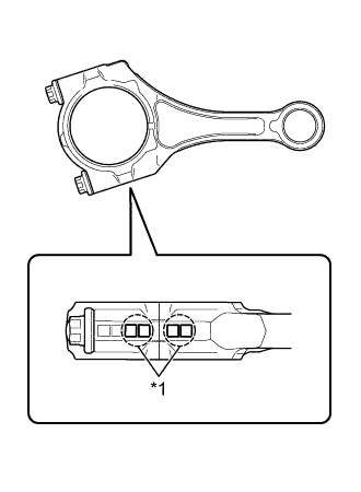
Check the matching symbols and set the connecting rod, connecting rod cap and connecting rod cap bolts.
| *1 | Matching Symbol |
Apply engine oil to the threads of the connecting rod cap bolts.
![]() |
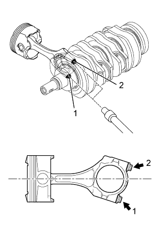
Using a "TORX" socket wrench E14, tighten the 2 connecting rod cup bolts in the order shown in the illustration.
Retighten the 2 connecting rod cup bolts in the same order as above. <*2>
In the same procedures from <*1> to <*2>, install the No. 2, No. 3 and No. 4 piston with connecting rods.
![]() |
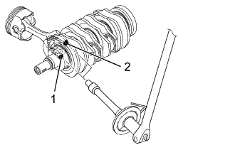
Using a "TORX" socket wrench E14 and an angle gauge, tighten the connecting rod cup bolts for the No. 1 to No. 4 piston with connecting rods by additional 92.5°.
![]() |
Using a feeler gauge, measure the thrust clearance for each connecting rod.
| 15. INSPECT CONNECTING ROD OIL CLEARANCE |
Clean the connecting rod bearings and crank pins, and apply engine oil to the crank pins. <*1>
Attach the connecting rod bearings to the connecting rod and connecting rod cap.
![]() |
Lay a strip of Plastigage across the crank pin, and set the connecting rod and the connecting rod cap with the 2 connecting rod cap bolts after checking the matching symbols.
| *1 | Matching Symbol |
Apply engine oil to the threads of the connecting rod cap bolts.
![]() |
Using a "TORX" socket wrench E14, tighten the 2 connecting rod cup bolts in the order shown in the illustration.
Retighten the 2 connecting rod cup bolts in the same order as above. <*2>
In the same procedures from <*1> to <*2>, install the No. 2, No. 3 and No. 4 piston with connecting rods.
![]() |
Using a "TORX" socket wrench E14 and an angle gauge, tighten the connecting rod cup bolts for the No. 1 to No. 4 piston with connecting rods by additional 92.5°.
![]() |
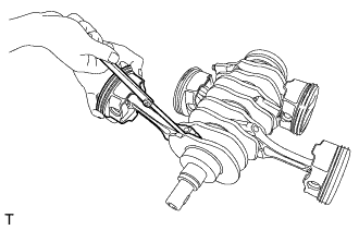
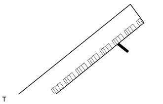
Remove the connecting rod cup and measure the Plastigage at its widest point.
| Bearing | Bearing size (Thickness at center) | Outer diameter of crank pin |
| Standard | 1.492 to 1.508 mm (0.05874 to 0.05937 in.) | 49.976 to 50.000 mm (1.96756 to 1.96850 in.) |
| 0.03 mm (0.0012 in.) Undersize | 1.511 to 1.515 mm (0.05949 to 0.05965 in.) | 49.946 to 49.970 mm (1.96637 to 1.96732 in.) |
| 0.05 mm (0.0020 in.) Undersize | 1.521 to 1.525 mm (0.05988 to 0.06004 in.) | 49.926 to 49.950 mm (1.96559 to 1.96653 in.) |
| 0.25 mm (0.0098 in.) Undersize | 1.621 to 1.625 mm (0.06382 to 0.06398 in.) | 49.726 to 49.750 mm (1.95771 to 1.95866 in.) |
| 16. INSPECT CRANKSHAFT |
Using a dye penetrant, check the important sections for fissures.
![]() |
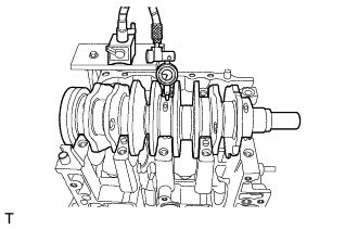
Using a dial indicator, measure the circle runout at the center journal.
![]() |
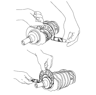
Using a micrometer, check the outer diameter of the crankshaft journal and crank pin for taper and out-of-round.
| Taper | 0.006 mm (0.00024 in.) |
| Out-of-runout | 0.005 mm (0.00020 in.) |
| Taper | 0.006 mm (0.00024 in.) |
| Out-of-runout | 0.005 mm (0.00020 in.) |
| Pin | 49.726 mm (1.95771 in.) |
| Journal | 67.735 mm (2.66673 in.) |
| Bearing | Connecting rod bearing thickness (at center) | Crank pin outer diameter | Crank bearing thickness (at center) | Crankshaft journal diameter | |
| No. 1 to No. 4 | No. 5 | ||||
| Standard | 1.492 to 1.508 mm (0.05874 to 0.05937 in.) | 49.976 to 50.000 mm (1.96756 to 1.96850 in.) | 2.498 to 2.513 mm (0.09835 to 0.09894 in.) | 2.496 to 2.511 mm (0.09827 to 0.09886 in.) | 67.985 to 68.003 mm (2.67657 to 2.67728 in.) |
| 0.03 mm (0.0012 in.) Undersize | 1.511 to 1.515 mm (0.05949 to 0.05965 in.) | 49.946 to 49.970 mm (1.96637 to 1.96734 in.) | 2.519 to 2.522 mm (0.09917 to 0.09929 in.) | 2.517 to 2.520 mm (0.09909 to 0.09921 in.) | 67.955 to 67.979 mm (2.67539 to 2.67633 in.) |
| 0.05 mm (0.0020 in.) Undersize | 1.521 to 1.525 mm (0.05988 to 0.06004 in.) | 49.926 to 49.950 mm (1.96559 to 1.96653 in.) | 2.529 to 2.532 mm (0.09957 to 0.09968 in.) | 2.527 to 2.530 mm (0.09949 to 0.09961 in.) | 67.935 to 67.959 mm (2.67460 to 2.67555 in.) |
| 0.25 mm (0.0098 in.) Undersize | 1.621 to 1.625 mm (0.06382 to 0.06398 in.) | 49.726 to 49.750 mm (1.95771 to 1.95866 in.) | 2.629 to 2.632 mm (0.10350 to 0.10362 in.) | 2.627 to 2.630 mm (0.10342 to 0.10354 in.) | 67.735 to 67.759 mm (2.66673 to 2.66767 in.) |
| 17. INSPECT CRANKSHAFT BEARING |
Inspect the crankshaft bearing for scar, peeling, seizure, melting or wear, etc.
| 18. INSPECT CRANKSHAFT THRUST CLEARANCE |
![]() |
Using a feeler gauge, check the thrust clearance of the crankshaft at No. 5 crankshaft bearing.
| 19. INSPECT CRANKSHAFT OIL CLEARANCE |
Remove the seal packing left on the cylinder block.
Clean the crankshaft bearings and crankshaft journals.
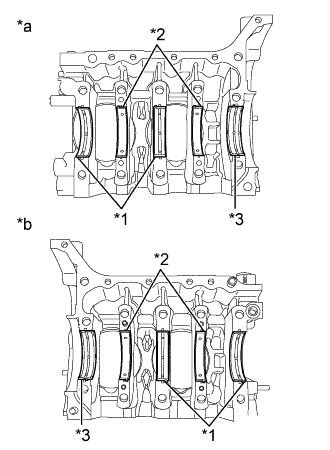
![]() |
Attach the crankshaft bearings to the cylinder block.
| *1 | No. 1 and No. 3 crankshaft bearings (with grooves) |
| *2 | No. 2 and No. 4 crankshaft bearings (without grooves) |
| *3 | No. 5 crankshaft bearings |
| *a | for Bank 1 |
| *b | for Bank 2 |
Place the crankshaft on the cylinder block.
Lay a strip of Plastigage across each camshaft journal.
Place the cylinder block (for bank 1) on the cylinder block (for bank 2).
Apply engine oil to the washers and cylinder block bolt threads.
![]() |
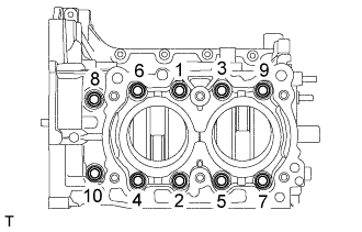
Using a 12 mm socket wrench, tighten the 10 bolts in the order shown in the illustration.
![]() |
Using a 12 mm socket wrench, loosen the 10 bolts by 180 ° in the order shown in the illustration.
![]() |
Using a 12 mm socket wrench, tighten the 10 bolts in the order shown in the illustration.
![]() |
Using a 12 mm socket wrench, loosen the 4 bolts by 180 ° in the order shown in the illustration.
![]() |
Using a 12 mm socket wrench, tighten the 4 bolts in the order shown in the illustration.
![]() |
Using a 12 mm socket wrench and an angle gauge, tighten the 4 bolts by additional 60° in the order shown in the illustration.
![]() |
Using a 12 mm socket wrench, loosen the 6 bolts by 180 ° in the order shown in the illustration.
![]() |
Using a 12 mm socket wrench, tighten the 6 bolts in the order shown in the illustration.
![]() |
Using a 12 mm socket wrench and an angle gauge, tighten the 3 bolts by additional 60° in the order shown in the illustration.
![]() |
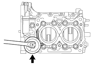
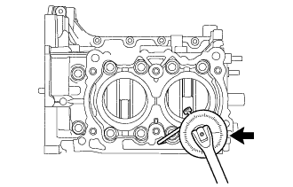
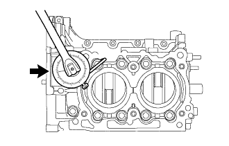
Using a 12 mm socket wrench and an angle gauge, tighten the bolt shown in the illustration by additional 80°.
![]() |
Using a 12 mm socket wrench and an angle gauge, tighten the bolt shown in the illustration by additional 60°.
![]() |
Using a 12 mm socket wrench and an angle gauge, tighten the bolt shown in the illustration by additional 80°.
![]() |
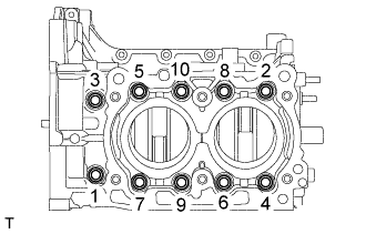
Using a 12 mm socket wrench, loosen the 10 bolts by 180 ° in the order shown in the illustration.
Remove the 10 bolts and cylinder block (for bank 1).
![]() |
Measure the Plastigage at its widest point.
| Bearing | Connecting rod bearing thickness (at center) | Crank pin outer diameter | Crank bearing thickness (at center) | Crankshaft journal diameter | |
| No. 1 to No. 4 | No. 5 | ||||
| Standard | 1.492 to 1.508 mm (0.05874 to 0.05937 in.) | 49.976 to 50.000 mm (1.96756 to 1.96850 in.) | 2.498 to 2.513 mm (0.09835 to 0.09894 in.) | 2.496 to 2.511 mm (0.09827 to 0.09886 in.) | 67.985 to 68.003 mm (2.67657 to 2.67728 in.) |
| 0.03 mm (0.0012 in.) Undersize | 1.511 to 1.515 mm (0.05949 to 0.05965 in.) | 49.946 to 49.970 mm (1.96637 to 1.96734 in.) | 2.519 to 2.522 mm (0.09917 to 0.09929 in.) | 2.517 to 2.520 mm (0.09909 to 0.09921 in.) | 67.955 to 67.979 mm (2.67539 to 2.67633 in.) |
| 0.05 mm (0.0020 in.) Undersize | 1.521 to 1.525 mm (0.05988 to 0.06004 in.) | 49.926 to 49.950 mm (1.96559 to 1.96653 in.) | 2.529 to 2.532 mm (0.09957 to 0.09968 in.) | 2.527 to 2.530 mm (0.09949 to 0.09961 in.) | 67.935 to 67.959 mm (2.67460 to 2.67555 in.) |
| 0.25 mm (0.0098 in.) Undersize | 1.621 to 1.625 mm (0.06382 to 0.06398 in.) | 49.726 to 49.750 mm (1.95771 to 1.95866 in.) | 2.629 to 2.632 mm (0.10350 to 0.10362 in.) | 2.627 to 2.630 mm (0.10342 to 0.10354 in.) | 67.735 to 67.759 mm (2.66673 to 2.66767 in.) |