CYLINDER HEAD > INSPECTION |
| 1. INSPECT CYLINDER HEAD SUB-ASSEMBLY |
Visually check that there are no cracks, scratches or other damage.
Using a dye penetrant, check the important sections for fissures.
Check that there are no signs of gas leak or water leak on gasket attachment surfaces.
Using a precision straightedge and a feeler gauge, measure the surfaces that contact the cylinder block for warpage.
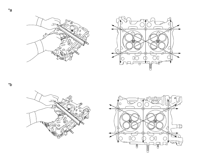
| *a | for Bank 1 | *b | for Bank 2 |
| 2. INSPECT INTAKE VALVE |
Check the valve flange and valve stem for damage, wear or deformation.
![]() |
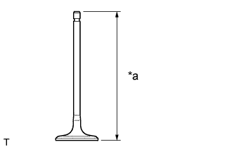
Using a vernier caliper, measure the overall length of the valve.
| *a | Overall Length |
![]() |
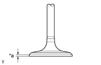
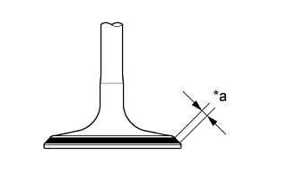
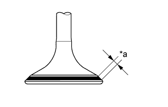
Using a vernier caliper, measure the valve head margin thickness.
| *a | Margin thickness |
![]() |
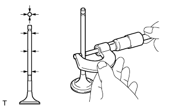
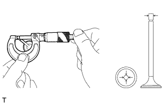
Using a micrometer, measure the diameter of the valve stem.
| 3. INSPECT EXHAUST VALVE |
Check the valve flange and valve stem for damage, wear or deformation.
![]() |
Using a vernier caliper, measure the overall length of the valve.
| *a | Overall Length |
![]() |
Using a vernier caliper, measure the valve head margin thickness.
| *a | Margin thickness |
![]() |
Using a micrometer, measure the diameter of the valve stem.
| 4. INSPECT VALVE GUIDE BUSH OIL CLEARANCE |
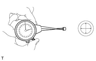
![]() |
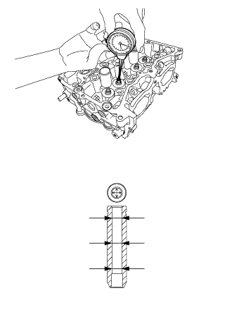
Using a caliper gauge, measure the inside diameter of the valve guide bush.
Calculate the clearance between the valve guide bush and valve stem.
| Item | Specified Condition |
| Intake | 0.030 to 0.057 mm (0.00118 to 0.00224 in.) |
| Exhaust | 0.040 to 0.067 mm (0.00157 to 0.00264 in.) |
| 5. INSPECT VALVE ADJUSTING SHIM CLEARANCE |
Visually check the valve adjusting shim for damage.
![]() |
Using a micrometer, measure the valve stem end diameter.
| Item | Specified Condition |
| Intake | 5.455 to 5.470 mm (0.21476 to 0.21535 in.) |
| Exhaust | 5.445 to 5.460 mm (0.21437 to 0.21496 in.) |
![]() |
Using a caliper gauge, measure the inside diameter of the valve adjusting shim.
Calculate the clearance between the valve adjusting shim and valve stem end.
| Item | Specified Condition |
| Intake | 0.030 to 0.105 mm (0.00118 to 0.00413 in.) |
| Exhaust | 0.040 to 0.115 mm (0.00157 to 0.00453 in.) |
| 6. INSPECT INTAKE VALVE SEATS |
Visually check the valve seat for damage or deformation.
Clean the valve and valve seat.
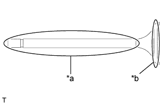
![]() |
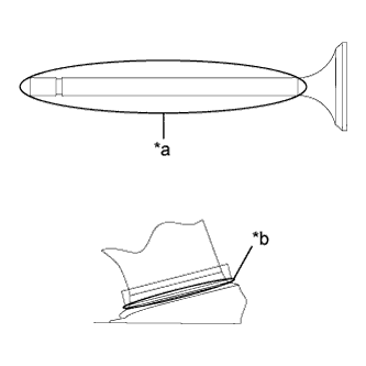
Apply a light coat of engine oil to the valve stem, and a light coat of Prussian blue uniformly to the valve face.
| *a | Valve stem |
| *b | Valve face |
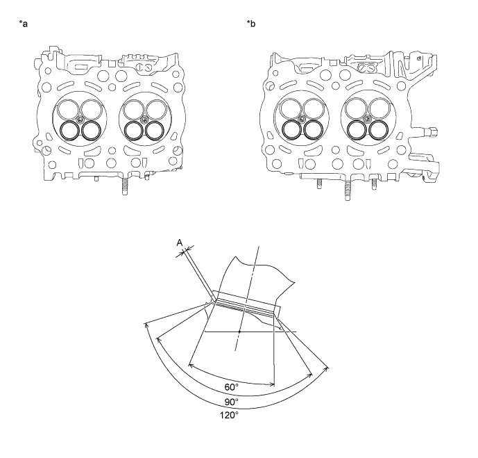
Insert the valve, and without rotating the valve, lightly press the valve face against the valve seat, and then pull it out.
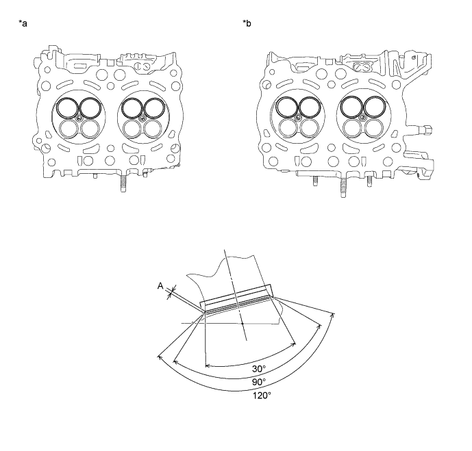
Using a vernier caliper, measure the width of the contact face shown in the illustration.

| *a | for Bank 1 | *b | for Bank 2 |
Completely remove the Prussian blue from the valve and valve seat.
![]() |
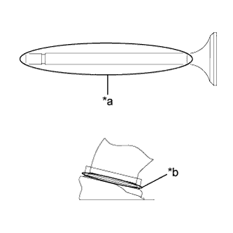
Apply a light coat of engine oil to the valve stem, and a light coat of Prussian blue uniformly to the valve seat face.
| *a | Valve stem |
| *b | Contact face |
Insert the valve, and without rotating the valve, lightly press the valve face against the valve seat, and then pull it out.
![]() |
Check the location of the contact face shown in the illustration.
| *a | Contact face location |
Completely remove the Prussian blue from the valve and valve seat.
| 7. INSPECT EXHAUST VALVE SEATS |
Visually check the valve seat for damage or deformation.
Clean the valve and valve seat.
![]() |
Apply a light coat of engine oil to the valve stem, and a light coat of Prussian blue uniformly to the valve face.
| *a | Valve stem |
| *b | Valve face |
Insert the valve, and without rotating the valve, lightly press the valve face against the valve seat, and then pull it out.
Using a vernier caliper, measure the width of the contact face shown in the illustration.

| *a | for Bank 1 | *b | for Bank 2 |
Completely remove the Prussian blue from the valve and valve seat.
![]() |
Apply a light coat of engine oil to the valve stem, and a light coat of Prussian blue uniformly to the valve seat face.
| *a | Valve stem |
| *b | Contact face |
Insert the valve, and without rotating the valve, lightly press the valve face against the valve seat, and then pull it out.
![]() |
Check the location of the contact face shown in the illustration.
| *a | Contact face location |
Completely remove the Prussian blue from the valve and valve seat.
| 8. INSPECT VALVE SPRING |
Visually check the valve spring for damage or deformation.
![]() |
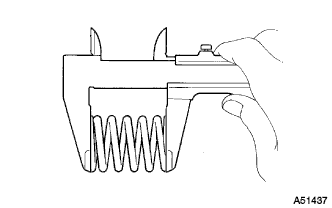
Using a vernier caliper, measure the free length of the valve spring.
![]() |
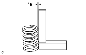
Using a steel square, measure the deviation of the valve spring.
| *a | Deviation |