 |
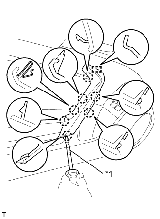
Using a screwdriver with its tip wrapped in protective tape, disengage the 7 claws.
FRONT DOOR > DISASSEMBLY |
| 1. DISCONNECT CABLE FROM NEGATIVE BATTERY TERMINAL |
| 2. REMOVE DOOR ARMREST COVER |
|
Using a screwdriver with its tip wrapped in protective tape, disengage the 7 claws.
Disengage the guides and remove the door armrest cover.
| *1 | Protective Tape |
| 3. REMOVE COURTESY LIGHT ASSEMBLY (w/ Courtesy Light) |
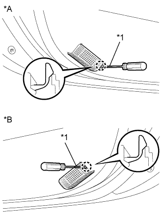 |
Using a screwdriver with its tip wrapped with protective tape, disengage the claw.
| *A | for LH Side |
| *B | for RH Side |
| *1 | Protective Tape |
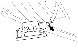 |
Disconnect the connector and remove the courtesy light assembly.
| 4. REMOVE FRONT DOOR TRIM BOARD SUB-ASSEMBLY |
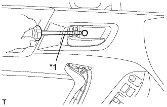 |
Using a screwdriver with its tip wrapped in protective tape, open the cap.
| *1 | Protective Tape |
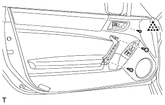 |
Using a clip remover, disengage the clip.
Remove the 3 screws.
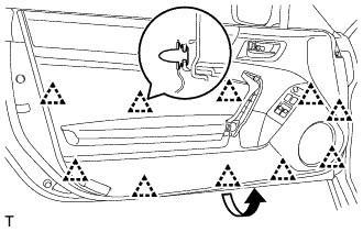 |
Using a moulding remover, disengage the 10 clips.
Pull out the front door trim board sub-assembly in the direction indicated by the arrow in the illustration.
Disconnect each connector.
Raise the front door trim board sub-assembly and remove the front door trim board sub-assembly together with the front door glass weatherstrip inner.
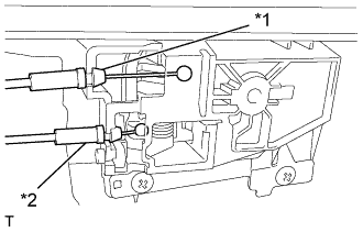 |
Disconnect the front door lock remote control cable and the front door inside locking cable.
| *1 | Front Door Inside Locking Cable |
| *2 | Front Door Lock Remote Control Cable |
| 5. REMOVE FRONT DOOR INSIDE HANDLE SUB-ASSEMBLY |
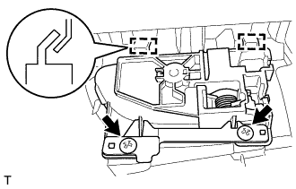 |
Remove the 2 screws.
Disengage the 2 guides and remove the front door inside handle sub-assembly.
| 6. REMOVE POWER WINDOW REGULATOR MASTER SWITCH ASSEMBLY WITH FRONT DOOR ARMREST BASE PANEL (for Driver Side) |
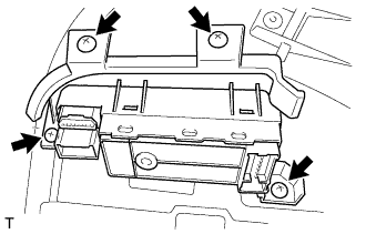 |
Remove the 4 screws and power window regulator master switch assembly with the front door armrest base panel.
| 7. REMOVE POWER WINDOW REGULATOR SWITCH ASSEMBLY WITH FRONT DOOR ARMREST BASE PANEL (for Front Passenger Side) |
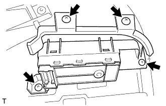 |
Remove the 4 screws and power window regulator switch assembly with front door armrest base panel.
| 8. REMOVE DOOR ASSIST GRIP ASSEMBLY |
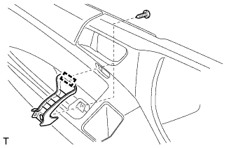 |
Remove the 2 screws.
Disengage the guide and remove the door assist grip assembly.
| 9. REMOVE FRONT LOWER DOOR TRIM PAD |
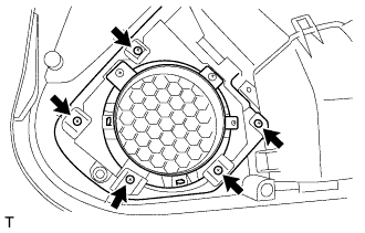 |
Remove the front lower door trim pad with the 5 screws.
| 10. REMOVE FRONT DOOR GLASS INNER WEATHERSTRIP |
Put a 4 mm (0.1575 in.) drill bit into a drill.
Wind tape around the drill bit approximately 5 mm (0.1969 in.) from the tip of the drill, as shown in the illustration.
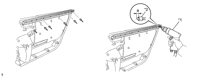
| *1 | Drill | *2 | Tape |
| a | 5.0 mm (0.1969 in.) | - | - |
Lightly press the drill against the 6 rivets and drill off the flanges of the 6 rivets.
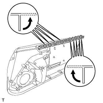 |
Disengage the 9 claws and remove the front door glass inner weatherstrip from the front door trim board sub-assembly, as shown in the illustration.
| 11. REMOVE FRONT DOOR SPEAKER HOLE COVER (w/o Front Speaker) |
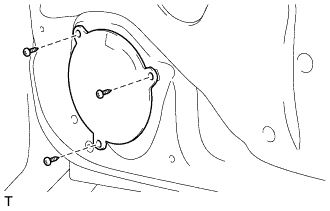 |
Remove the front door speaker hole cover with the 3 screws.
| 12. REMOVE FRONT NO. 1 SPEAKER ASSEMBLY (w/ Front Speaker) |
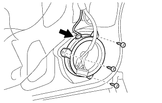 |
Disconnect the connector.
Remove the 3 screws and front No. 1 speaker assembly.
| 13. REMOVE FRONT DOOR SERVICE HOLE COVER |
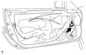 |
Disconnect the outer rear view mirror sub-assembly connector.
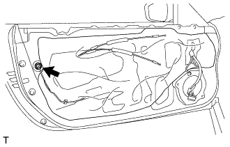 |
Disconnect the front door lock assembly connector.
Remove the front door service hole cover.
| 14. REMOVE OUTER REAR VIEW MIRROR SUB-ASSEMBLY |
Disengage the wire harness clip.
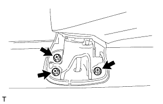 |
Remove the 3 bolts and the outer rear view mirror sub-assembly LH.
| 15. REMOVE FRONT DOOR GLASS SUB-ASSEMBLY |
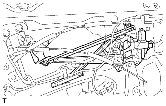 |
Provisionally install the power window regulator master switch (for driver side).
Provisionally install the power window regulator switch (for passenger side).
Connect the cable to the negative (-) battery terminal.
Move the front door glass sub-assembly until the 2 nuts can be seen through the service holes.
Disconnect the power window regulator master switch connector (for driver side).
Disconnect the power window regulator switch connector (for passenger side).
Disconnect the cable from the negative (-) battery terminal.
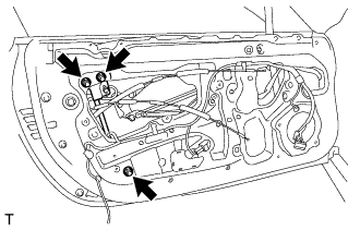 |
Remove the 3 nuts.
Shift the front door rear lower frame sub-assembly to the lower side of the door frame.
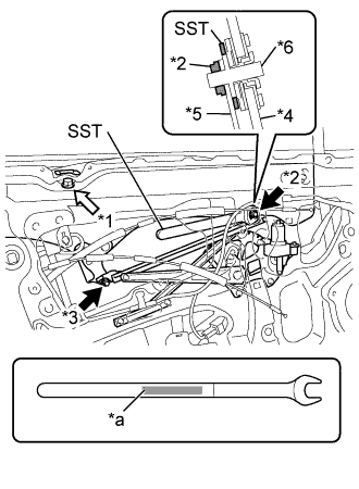 |
Install SST as shown in the illustration.
| *1 | Door Glass Inner Stabilizer Bolt |
| *2 | Nut A |
| *3 | Nut B |
| *4 | Front Door Glass Sub-assembly |
| *5 | Front Door Window Regulator Sub-assembly |
| *6 | Bolt |
| *a | SST Number |
Secure the bolt using SST, and then remove nut A.
Remove nut B from the front door glass sub-assembly.
Loosen the door glass inner stabilizer bolt.
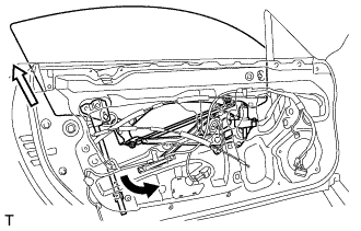 |
While holding the front door glass sub-assembly up, slide the front door rear lower frame sub-assembly downward, and pull the front door glass sub-assembly out from the front door rear lower frame sub-assembly.
Partially remove the rear end of the front door weatherstrip until the front door glass sub-assembly can be removed.
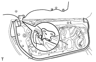 |
Remove the front door glass sub-assembly from the position indicated in the illustration.
| 16. REMOVE FRONT DOOR REAR LOWER FRAME SUB-ASSEMBLY |
Remove the front door rear lower frame sub-assembly from the front door frame.
| 17. REMOVE DOOR GLASS INNER STABILIZER |
Remove the bolt and the door glass inner stabilizer.
| 18. REMOVE FRONT DOOR SUSH |
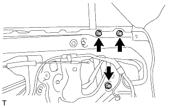 |
Remove the 3 nuts.
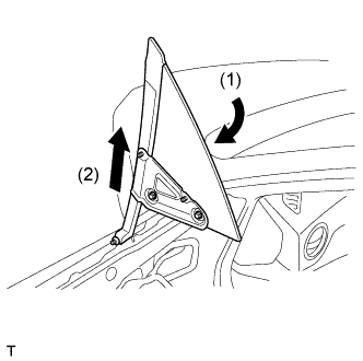 |
Rotate the front door sush as indicated by the arrows in the order shown in the illustration, and remove the front door sush.
| 19. REMOVE FRONT DOOR SASH STOPPER |
Remove the nut and front door sush stopper.
| 20. REMOVE FRONT DOOR WINDOW REGULATOR SUB-ASSEMBLY |
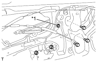 |
Disconnect the connector.
Loosen the temporary bolt.
| *1 | Temporary Bolt |
Remove the 3 bolts and 2 nuts.
Remove the temporary bolt and the front door window regulator sub-assembly with power window regulator motor assembly.
| 21. REMOVE POWER WINDOW REGULATOR MOTOR ASSEMBLY |
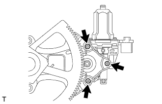 |
Using a T25 "TORX" socket wrench, remove the 3 screws and the power window regulator motor assembly.
| 22. REMOVE FRONT DOOR WEATHERSTRIP |
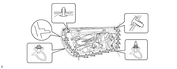
Disengage the 2 claws and remove the screw.
Using a clip remover, disengage the 16 clips and remove the front door weatherstrip.
| 23. REMOVE FRONT DOOR LOCK CYLINDER ASSEMBLY (for Driver Side) |
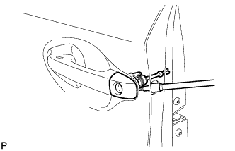 |
Using a T30 "TORX" socket wrench, loosen the screw and remove the front door lock cylinder assembly with front door outside handle cover LH.
| 24. REMOVE FRONT DOOR OUTSIDE HANDLE COVER (for Driver Side) |
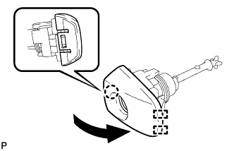 |
Using a screwdriver, disengage the claw and 2 guides and remove the front door outside handle cover, as shown in the illustration.
| 25. REMOVE FRONT DOOR OUTSIDE HANDLE COVER (for Front Passenger Side) |
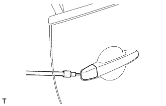 |
Using a T30 "TORX" socket wrench, loosen the screw and remove the front door outside handle cover.
| 26. REMOVE FRONT DOOR LOCK ASSEMBLY |
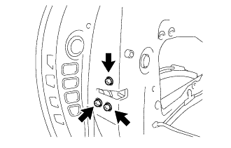 |
Remove the 3 bolts.
Slide the front door lock assembly downward, pull out the front door lock open rod from the outside handle frame, and remove the front door lock assembly and cables as a unit.
| 27. REMOVE FRONT DOOR OUTSIDE HANDLE ASSEMBLY (w/o Entry and Start System) |
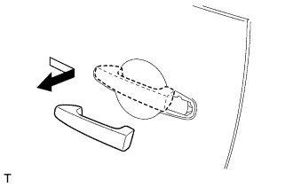 |
Remove the front door outside handle assembly, as shown in the illustration.
| 28. REMOVE FRONT DOOR OUTSIDE HANDLE ASSEMBLY (w/ Entry and Start System) |
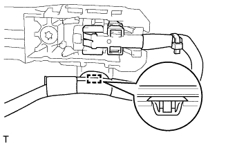 |
Disengage the clamp.
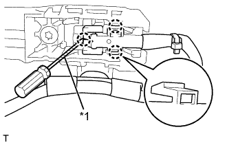 |
Using a screwdriver with its tip wrapped in protective tape, disengage the 3 claws.
| *1 | Protective Tape |
Disconnect the connector.
|
Remove the front door outside handle assembly, as shown in the illustration.
| 29. REMOVE FRONT DOOR FRONT OUTSIDE HANDLE PAD |
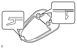 |
Disengage the 3 claws and remove the front door front outside handle pad.
| 30. REMOVE FRONT DOOR REAR OUTSIDE HANDLE PAD |
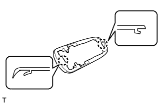 |
Disengage the 2 claws and remove the front door rear outside handle pad.
| 31. REMOVE FRONT DOOR OUTSIDE HANDLE FRAME SUB-ASSEMBLY |
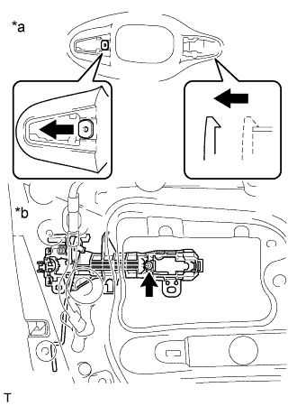 |
Using a T30 "TORX" socket wrench, loosen the screw.
Slide the front door outside handle frame sub-assembly to disengage the claw of the front door outside handle frame sub-assembly, and then remove it.
| *a | Outside Vehicle |
| *b | Inside Vehicle |
| 32. REMOVE FRONT DOOR LOCK OPEN ROD |
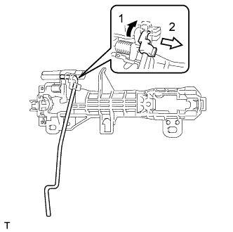 |
Remove the front door lock open rod as indicated by the arrows, in the order shown in the illustration.
| 33. REMOVE FRONT DOOR CHECK ASSEMBLY |
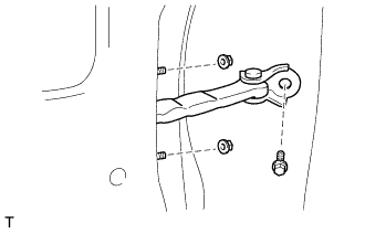 |
Remove the bolt.
Remove the 2 nuts and front door check assembly.
| 34. REMOVE FRONT DOOR PANEL CUSHION |
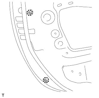 |
Disengage the 2 claws and remove the 2 front door panel cushions.
| 35. REMOVE FRONT DOOR GLASS OUTER WEATHERSTRIP ASSEMBLY |
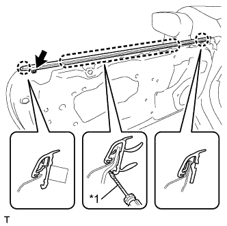 |
Remove the screw.
| *1 | Protective Tape |
Using a screwdriver, disengage the claw and remove the front door glass outer weatherstrip assembly.
| 36. REMOVE DOOR SIDE AIR BAG SENSOR |
Check that the ignition switch is off.
Check that the cable is disconnected from the negative (-) battery terminal.
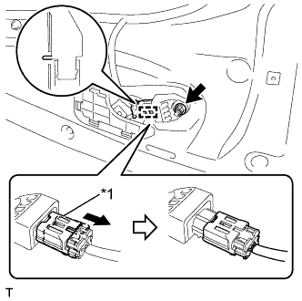 |
Remove the nut and separate the door side airbag sensor from the front door panel.
Slide the outer housing to release the lock, and then disconnect the connector to remove the door side airbag sensor.
| *1 | Outer Housing |
| 37. REMOVE FRONT DOOR HOLE COVER |
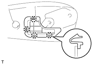 |
Disengage the 4 claws and remove the front door hole cover.