Home › Engine / Hybrid System › FA20 FUEL › FUEL SENDER GAUGE ASSEMBLY

FUEL SENDER GAUGE ASSEMBLY > INSPECTION

for Preparation Click here


1. INSPECT FUEL SENDER GAUGE ASSEMBLY

CAUTION:
Take special care of fire.

  1. Inspect to see if there is any damage to the fuel sender gauge assembly.


    A280569E01
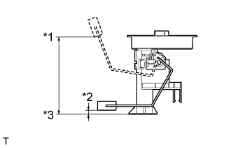
  1. Measure the dimensions between the fuel tank seat face and the float center with the float position at F (upper end) and at E (lower end).
    Dimensions 
    Float position F (upper end) to fuel tank seat face
    121 to 129 mm (4.764 to 5.079 in.)
    Float position E (lower end) to fuel tank seat face
    14.7 to 22.7 mm (0.579 to 0.894 in.)
    Text in Illustration 
    *1
    Float position F (upper end)
    *2
    Float position E (lower end)
    *3
    Fuel tank seat face

  1. Check that the float moves smoothly between F (upper) and E (lower).


    A282939E01
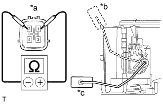
  1. Measure the resistance according to the value(s) in the table below.

    Standard Resistance:
    Tester Connection
    Condition
    Specified Condition
    1 - 2
    Float position is F (upper end)
    6.5 to 8.5 Ω
    Float position is E (lower end)
    168 to 172 Ω

    Text in Illustration 
    *a
    Component without harness connected
    (Fuel Sender Gauge Assembly)
    *b
    F (upper end)
    *c
    E (lower end)
    If the value is not as specified, replace the fuel sender gauge assembly.


2. INSPECT NO. 2 FUEL SENDER GAUGE ASSEMBLY

CAUTION:
Take special care of fire.

  1. Inspect to see if there is any damage to the No. 2 fuel sender gauge assembly.


    A280576E01
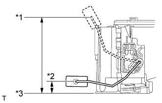
  1. Measure the dimensions between the fuel tank seat face and the float center with the float position at F (upper end) and at E (lower end).
    Dimensions 
    Float position F (upper end) to fuel tank seat face
    150.3 to 158.3 mm (5.917 to 6.232 in.)
    Float position E (lower end) to fuel tank seat face
    0.7 to 8.7 mm (0.028 to 0.343 in.)
    Text in Illustration 
    *1
    Float position F (upper end)
    *2
    Float position E (lower end)
    *3
    Fuel tank seat face

  1. Check that the float moves smoothly between F (upper) and E (lower).


    A280577E02
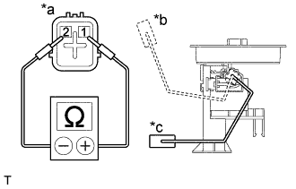
  1. Measure the resistance according to the value(s) in the table below.

    Standard Resistance:
    Tester Connection
    Condition
    Specified Condition
    1 - 2
    Float position is F (upper end)
    5.5 to 9.5 Ω
    Float position is E (lower end)
    236 to 244 Ω

    Text in Illustration 
    *a
    Component without harness connected
    (No. 2 Fuel Sender Gauge Assembly)
    *b
    F (upper end)
    *c
    E (lower end)
    If the value is not as specified, replace the fuel sender gauge assembly.