 |
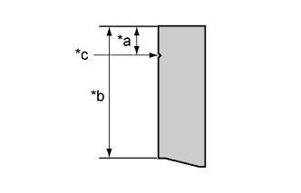
Using a vernier caliper, measure the brush length.
- Standard length:
- 22.5 mm (0.885 in)
- Minimum length:
- 5.0 mm (0.196 in)
| *a | Minimum length |
| *b | Standard length |
| *c | Mark of minimum length |
 | Brush |
GENERATOR > INSPECTION |
| 1. INSPECT BRUSH |
|
Using a vernier caliper, measure the brush length.
| *a | Minimum length |
| *b | Standard length |
| *c | Mark of minimum length |
| Brush |
| 2. INSPECT GENERATOR COIL ASSEMBLY |
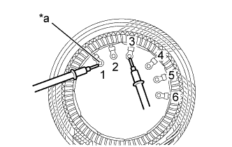 |
Check the resistance.
Measure the resistance according to the value(s) in the table below.
| Tester Connection | Condition | Specified Condition |
| 1 - 2 | Always | Below 1 Ω |
| 1 - 3 | ||
| 2 - 3 | ||
| 4 - 5 | ||
| 4 - 6 | ||
| 5 - 6 |
| *a | Lead wire |
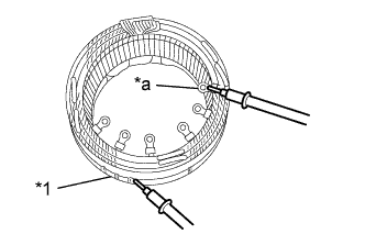 |
Check the resistance.
Measure the resistance according to the value(s) in the table below.
| Tester Connection | Condition | Specified Condition |
| Stator core - Lead wire | Always | 10 kΩ or higher |
| *1 | Stator core |
| *a | Lead wire |
| 3. INSPECT GENERATOR ROTOR ASSEMBLY |
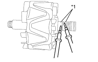 |
Check the generator rotor assembly for open circuits.
Measure the resistance according to the value(s) in the table below.
| Tester Connection | Condition | Specified Condition |
| Slip ring - Slip ring | 20°C (68°F) | 2.0 to 2.4 Ω |
| *1 | Slip Ring |
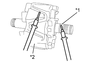 |
Check if the generator rotor assembly is grounded.
Measure the resistance according to the value(s) in the table below.
| Tester Connection | Condition | Specified Condition |
| Slip ring - Rotor core | Always | 10 kΩ or higher |
| *1 | Slip Ring |
| *2 | Rotor Core |
Check the slip ring diameter.
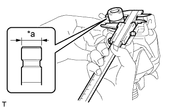 |
Using a vernier caliper, measure the diameter of each slip ring.
| *a | Diameter of Slip Ring |
| 4. INSPECT GENERATOR HOLDER WITH RECTIFIER |
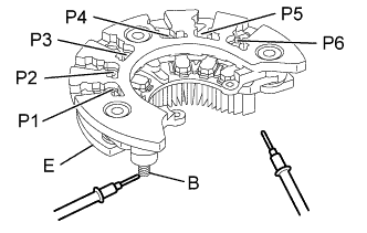 |
Check the resistance.
Measure the resistance according to the value(s) in the table below.
| Tester Connection | Condition | Specified Condition |
| P1, P2, P3, P4, P5, P6 - B | P1, P2, P3, P4, P5, P6 (Tester positive) B (Tester negative) | Below 1 Ω |
| P1, P2, P3, P4, P5, P6 (Tester negative) B (Tester positive) | 10 kΩ or higher | |
| P1, P2, P3, P4, P5, P6 - E | P1, P2, P3, P4, P5, P6 (Tester positive) E (Tester negative) | 10 kΩ or higher |
| P1, P2, P3, P4, P5, P6 (Tester negative) E (Tester positive) | Below 1 Ω |