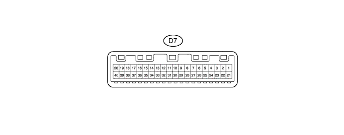
METER / GAUGE SYSTEM > TERMINALS OF ECU |
| CHECK COMBINATION METER ASSEMBLY |
Measure the voltage and resistance of the wire harness side connector.
| Terminals No. (Symbol) | Wiring Color | Terminal Description | Condition | Specified Condition |
| D7-1 (B) - Body ground | R-W - Body ground | Battery | Always | 11 to 14 V |
| D7-2 (IG+) - Body ground | W-G - Body ground | Ignition switch signal | Ignition switch off → ON | Below 1 V → 11 to 14 V |
| D7-4 (LED LO) - Body ground | P-B - Body ground | LED headlight warning signal | Ignition switch ON LED warning light ON → OFF | Below 1 V → 11 to 14 V |
| D7-6 (CANH) - Body ground | BR - Body ground | CAN communication line | Ignition switch ON | Pulse generation |
| D7-7 (CANL) - Body ground | BR-W - Body ground | CAN communication line | Ignition switch ON | Pulse generation |
| D7-9 (ILL-) - Body ground | B-W - Body ground | Light control rheostat output signal | Ignition switch ON Light control rheostat all top open → all bottom open | Below 1 V → 11 to 14 V |
| D7-13 (P/SB) - Body ground | BR-R - Body ground | Front passenger seat inner belt output signal | Front passenger seat is occupied and its seat belt unfastened → fastened | Below 1 V → 11 to 14 V |
| D7-14 (S) - Body ground | LG - Body ground | Engine oil pressure signal | Engine oil pressure warning light ON → OFF | Below 1 V → 11 to 14 V |
| D7-15 (CHG-) - Body ground | G - Body ground | Charge warning light signal | Engine start Charge warning light ON → OFF | Below 1 V → 11 to 14 V |
| D7-17 (LBL) - Body ground | W-L - Body ground | Brake fluid level warning light signal | Ignition switch ON Brake fluid level warning light ON → OFF | Below 1 V → 11 to 14 V |
| D7-18 (IND) - Body ground | V - Body ground | Security warning light signal | Ignition switch ON Security warning light blink → OFF | Below 1 V ←→11 to 14 V→ 11 to 14 V |
| D7-19 (LVWG) - Body ground | Y - Body ground | Head light level warning light signal | Ignition switch ON Head light level warning light ON → OFF | Below 1 V → 11 to 14 V |
| D7-20 (ES1) - Body ground | B-Y - Body ground | Ground | Always | Below 1 Ω |
| D7-21 (LR) - Body ground | GR - Body ground | Right turn signal | Ignition switch ON Right turn indicator light blink → OFF | Below 1 V ←→11 to 14 V→ 11 to 14 V |
| D7-22 (LL) - Body ground | W-R - Body ground | Left turn signal | Ignition switch ON Left turn indicator light blink → OFF | Below 1 V ←→11 to 14 V→ 11 to 14 V |
| D7-23 (+DP) - Body ground*1 | L-W - Body ground | Steering pad switch signal | Ignition switch ON up, down, right and left switches on steering pad switch assembly not pushed | 4.8 to 5.2 V |
| Ignition switch ON Up, down, right or left switches on steering pad switch assembly pushed | Below 1 V | |||
| D7-24 (TAM) - D7-25 (SG-) | L - W | Ambient temperature sensor signal | Ignition switch ON at 25°C (77°F) | 1.35 to 1.75 V |
| D7-26 (+DP2) - Body ground*1 | BR-W - Body ground | Steering pad switch signal | Ignition switch ON Enter and back switches on steering pad switch assembly not pushed | 4.8 to 5.2 V |
| Ignition switch ON Enter or back switches on steering pad switch assembly pushed | Below 1 V | |||
| D7-27 (L) - D7-28 (FS-) | LG - L | Fuel level signal | Fuel level is FULL → EMPTY | Below 1 V → 4.5 to 9.0 V |
| D7-30 (E) - Body ground | L-R - Body ground | Light control rheostat ground | Always | Below 1 Ω |
| D7-31 (TR) - Body ground | Y - Body ground | Light control rheostat input signal | Light control rheostat all top open → all bottom open | 510 Ω → 100 Ω |
| D7-32 (T) - Body ground | G-W - Body ground | Ignition switch signal | Ignition switch off → ON | Below 1 V → 3.6 to 4.6 V |
| D7-33 (TC) - Body ground | BR - Body ground | Light control rheostat signal | Light control rheostat all top open → Light control rheostat (cancel switch) ON | 10 kΩ or higher → Below 1 Ω |
| D7-34 (DISP) - Body ground | R - Body ground | DISP switch signal | DISP switch ON → OFF | Below 1 Ω → 10 kΩ or higher |
| D7-35 (CS) - Body ground*2 | O - Body ground | km/h / MPH switch signal | km/h / MPH switch ON → OFF | Below 1 Ω → 10 kΩ or higher |
| D7-36 (TRIP) - Body ground | P - Body ground | ODO/TRIP switch signal | ODO/TRIP switch ON → OFF | Below 1 Ω → 10 kΩ or higher |
| D7-37 (DBKL) - Body ground | R-B - Body ground | Driver seat inner belt input signal | Driver seat is seat belt unfastened → fastened | Below 1 V → 11 to 14 V |
| D7-38 (PBKL) - Body ground | R-G - Body ground | Front passenger seat inner belt input signal | Front passenger seat is occupied and its seat belt unfastened → fastened | Below 1 V → 11 to 14 V |
| D7-40 (ES2) - Body ground | B-Y - Body ground | Ground | Always | Below 1 Ω |