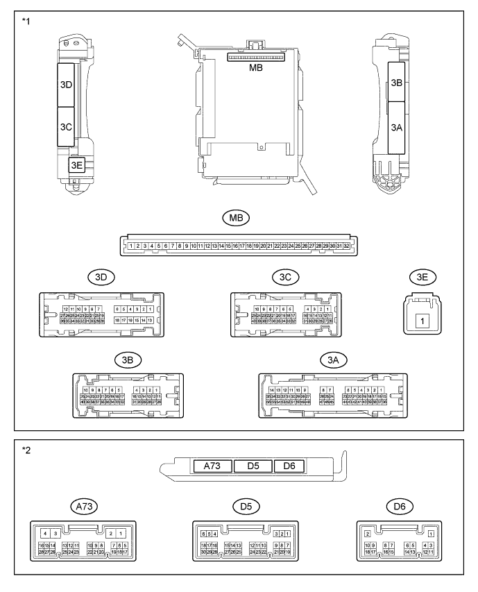
ELECTRIC POWER CONTROL SYSTEM > TERMINALS OF ECU |
| CHECK INSTRUMENT PANEL JUNCTION BLOCK ASSEMBLY AND MAIN BODY ECU (NETWORK GATEWAY ECU) |
| *1 | Instrument Panel Junction Block Assembly | *2 | Main Body ECU (Network Gateway ECU) |
Measure the voltage and resistance according to the value(s) in the table below.
| Terminal No. (Symbol) | Wiring Color | Terminal Description | Condition | Specified Condition |
| 3A-15 - Body ground | W - Body ground | IG power supply | Ignition switch ON | 11 to 14V |
| 3A-20 - Body ground | SB - Body ground | ACC power supply | Ignition switch ACC | 11 to 14V |
| 3A-27 - Body ground | G-R - Body ground | Battery power supply | Always | 11 to 14V |
| 3C-19 - Body ground | L-R - Body ground | Battery power supply | Always | 11 to 14V |
| 3E-1 - Body ground | B-R - Body ground | Battery power supply | Always | 11 to 14V |
| 3A-12 - Body ground | B - Body ground | Ground | Always | Below 1 Ω |
| 3A-13 - Body ground | B - Body ground | Ground | Always | Below 1 Ω |
| 3B-18 - Body ground | B-Y - Body ground | Ground | Always | Below 1 Ω |
| D6-1 (GND) - Body ground | B - Body ground | Ground | Always | Below 1 Ω |
| A73-4 (GND) - Body ground | B-Y - Body ground | Ground | Always | Below 1 Ω |
Remove the main body ECU (network gateway ECU) from the instrument panel junction block assembly.
Measure the voltage and resistance according to the value(s) in the table below.
| Terminal No. (Symbol) | Wiring Color | Terminal Description | Condition | Specified Condition |
| MB-1 (BECU) - Body ground | None - Body ground | Battery power supply back up voltage | Always | 11 to 14V |
| MB-8 (IG) - Body ground | None - Body ground | IG power supply | Ignition switch ON | 11 to 14V |
| MB-9 (ACC) - Body ground | None - Body ground | ACC power supply | Ignition switch ACC | 11 to 14V |
| MB-32 (BMPX) - Body ground | None - Body ground | Battery power supply control voltage | Always | 11 to 14V |
| MB-11 (GND) - Body ground | None - Body ground | Ground | Always | Below 1 Ω |