Disconnect the D59 steering lock actuator assembly (steering lock ECU) connector.

Measure the voltage and resistance according to the value(s) in the table below.
| Terminal No. (Symbol) | Input/Output | Wiring Color | Terminal Description | Condition | Specified Condition | Related Data List Item |
| D59-1 (GND) - Body ground | - | B - Body ground | Ground*2 | Always | Below 1 Ω | - |
| D59-3 (SLR+) - D59-1 (GND) | Input | Y - B | Steering lock motor activation command signal (motor activation command signal sent from certification ECU (smart key ECU assembly)) | Any door opened when conditions below met, and then steering lock motor activated:
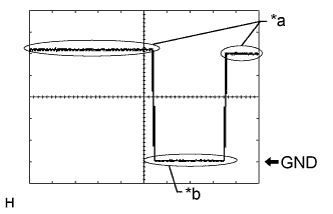
| Pulse generation (see waveform) | Entry & Start
|
| D59-4 (SLP) - D59-1 (GND) | Output | LG - B | Steering lock bar position signal (output signal from steering unlock sensor) | Steering locked → unlocked | 11 to 14 V → Below 1.2 V | Entry & Start
|
| D59-5 (LIN) - D59-1 (GND) | Input/Output | W - B | LIN communication line | - | - | Entry & Start
|
| D59-6 (IGN1) - D59-1 (GND) | Input | BR - B | Power source mode signal (IG2 power supply input for entire steering lock actuator assembly)*2 | Engine switch off → engine switch on (IG) | Below 1 V → 11 to 14 V | Entry & Start
|
| D59-7 (B) - Body ground | Input | SB - Body ground | Power source*2 | Always | 11 to 14 V | - |
- *1: for Automatic Transmission
- *2: When there is a problem with the power source input, the certification ECU (smart key ECU assembly) may store DTC B2786.
- NOTICE:
- There is 1 motor and 2 sensors built into the steering lock actuator assembly.
- HINT:
- When taking measurements when the lock motor is stopped, it is not necessary to perform any operations.
- In order to take measurements when the lock motor is operating, perform either of the following operations:
- To unlock the steering, carry the key and turn the engine switch on (ACC) or on (IG).
- To lock the steering, turn the engine switch off with the shift lever is in P*, and then open a door.
- *: for Automatic Transmission
Waveform
Item Content Tester Connection D59-3 (SLR+) - D59-1 (GND) Tool Setting 2 V/DIV., 200 ms./DIV. Vehicle Condition Steering lock motor not operating → Steering lock motor operating → Steering lock motor not operating Text in Illustration *a Steering lock motor not operating *b Steering lock motor operating
 |