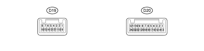
AIR CONDITIONING SYSTEM (for Automatic Air Conditioning System) > TERMINALS OF ECU |
| AIR CONDITIONING CONTROL ASSEMBLY |
| Terminal No. (Symbol) | Wiring Color | Description | Condition | Specified Condition |
| D19-1 (ACC) - D19-16 (GND) | R-B - B-Y | Power source (ACC) | Ignition switch : OFF | Below 1 V |
| Ignition switch : ACC | 10 to 16 V | |||
| D19-2 (PSW) - D20-6 (SG) | Y-B - LG | A/C pressure switch signal | Engine running A/C system operating Refrigerant pressure: Normal | 10 to 16 V |
| Engine running A/C system operating Refrigerant pressure: Abnormal | Below 1 V | |||
| D20-6 (SG) - Body ground | B-Y - Body ground | Ground for sensor and servo motor | Always | Below 1 Ω |
| D19-8 (HR) - D19-16 (GND) | V-Y - B-Y | Heater relay control signal | Blower switch : OFF Refrigerant, pressure: Normal | Below 1 V |
| Blower switch : ON Refrigerant, pressure: Normal | 10 to 16 V | |||
| D19-9 (+B) - D19-16 (GND) | L-R - B-Y | Power source (Back up) | Always | 10 to 16 V |
| D19-10 (IG) - D19-16 (GND) | G - B-Y | Power source (IG) | Ignition switch : OFF | Below 1 V |
| Ignition switch : IG | 10 to 16 V | |||
| D19-11 (ILL+) - D19-16 (GND) | V - B-Y | Tail indication light signal | Headlight switch : OFF | Below 1 V |
| Headlight switch : TAIL | 10 to 16 V | |||
| D19-12 (CANL) - D19-16 (GND) | L-Y - B-Y | CAN communication circuit | Ignition switch : ON | Pulse generation |
| D19-13 (CANH) - D19-16 (GND) | L-W - B-Y | CAN communication circuit | Ignition switch : ON | Pulse generation |
| D19-14 (BLW) - D19-16 (GND) | G-W - B-Y | Blower motor speed control signal | Ignition switch : ON Blower switch : ON | Pulse generation (See waveform 1) |
| D20-2 (CLTS) - Body ground | Y - Body ground | A/C solar sensor signal | Ignition switch : ON Solar sensor is subjected to electric light. | 0.8 to 4.3 V |
| D20-13 (S5) - D19-16 (GND) | W - B-Y | Power supply for sensor and servo motor | Ignition switch : ON | 4.75 to 5.25 V |
| COMBINATION METER |

| Terminal No. (Symbol) | Wiring Color | Description | Condition | Specified Condition |
| D7-24(TAM) - D7-25(SG-) | L - W | Ambient temperature sensor signal | Ignition switch : ON Ambient temperature at 25°C(77°F) | 1.4 to 1.6 V |
| D7-6(CANL) - Body ground | BR - Body ground | CAN communication circuit | Ignition switch : ON | Pulse generation |
| D7-7(CANH) - Body ground | BR-W - Body ground | CAN communication circuit | Ignition switch : ON | Pulse generation |
| INSTRUMENT PANEL JUNCTION BLOCK ASSEMBLY, MAIN BODY ECU (NETWORK GATEWAY ECU) |
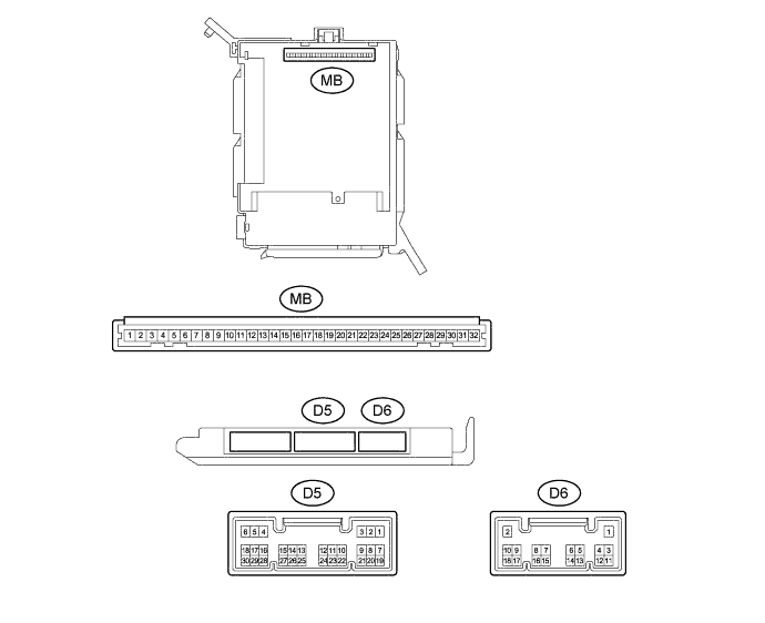
Remove the main body ECU (network gateway ECU) from the instrument panel junction block assembly.
Measure the values on the wire harness side with the connector disconnected.
| Terminal No. (Symbol) | Wiring Color | Description | Condition | Specified Condition |
| MB8(IG) - Body ground | - | Power source (IG) | Ignition switch : ON | 11 to 14 V |
| MB9(ACC) - Body ground | - | Power source (ACC) | Ignition switch : ACC | 11 to 14 V |
| MB11(GND) - Body ground | - | Ground for main power supply | Always | Below 1 Ω |
Install the main body ECU (network gateway ECU) to the instrument panel junction block assembly.
Measure the voltage and resistance according to the value(s) in the table below.
| Terminal No. (Symbol) | Wiring Color | Description | Condition | Specified Condition |
| D5-13(CANL) - D5-14(CANH) | LG - P | CAN communication circuit | Ignition switch : ON | Pulse generation |
| D6-13(CLTE) - Body ground | G - Body ground | Ground for solar sensor | Always | Below 1 Ω |
| D6-15(CLTB) - Body ground | R - Body ground | Power supply for solar sensor | Ignition switch : ON | 4.75 to 5.25 V |
| ECM |
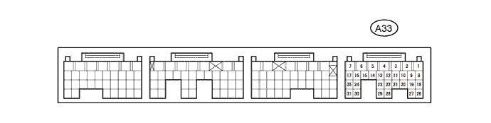
| Terminal No. (Symbol) | Wiring Color | Description | Condition | Specified Condition |
| A33-8(ACP) - Body ground | G - Body ground | Air conditioner pressure switch signal | Engine running A/C system operating Refrigerant pressure: Abnormal | Below 1 V |
| Engine running A/C system operating Refrigerant pressure: Normal | 10 to 16 V | |||
| A33-18(CANL) - A33-19(CANH) | B-P - O | CAN communication circuit | Ignition switch : ON | Pulse generation |