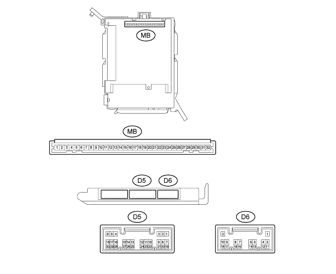
AIR CONDITIONING SYSTEM (for Manual Air Conditioning System) > TERMINALS OF ECU |
| INSTRUMENT PANEL JUNCTION BLOCK ASSEMBLY, MAIN BODY ECU (NETWORK GATEWAY ECU) |
Remove the main body ECU (network gateway ECU) from the instrument panel junction block assembly.
Measure the values on the wire harness side with the connector disconnected.
| Terminal No. (Symbol) | Wiring Color | Description | Condition | Specified Condition |
| MB8(G) - Body ground | - | Power source (IG) | Ignition switch : ON | 11 to 14 V |
| MB9(ACC) - Body ground | - | Power source (ACC) | Ignition switch : ACC | 11 to 14 V |
| MB11(GND) - Body ground | - | Ground for main power supply | Always | Below 1 Ω |
Install the main body ECU (network gateway ECU) to the instrument panel junction block assembly.
Measure the voltage and resistance according to the value(s) in the table below.
| Terminal No. (Symbol) | Wiring Color | Description | Condition | Specified Condition |
| D5- 13(CANL) - D5-14(CANH) | LG - P | CAN communication system | CAN communication circuit | Pulse generation |
| Terminal No. (Symbol) | Wiring Color | Description | Condition | Specified Condition |
| D6-17 - Body ground | Y - Body ground | A/C switch signal |
| Below 1 Ω |
| ECM |
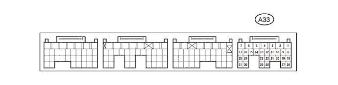
| Terminal No. (Symbol) | Wiring Color | Terminal Description | Condition | Specified Condition |
| A33-8(ACP) - Body ground | G - Body ground | Air conditioning pressure switch signal | Engine running A/C system operating Refrigerant pressure: Abnormal | Below 1 V |
| Engine running A/C system operating Refrigerant pressure: Normal | 11 to 14 V | |||
| A33- 18(CANL) - A33-19(CANH) | B-P - O | CAN communication system | CAN communication circuit | Pulse generation |