 |
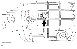
Remove the manual transmission filler plug and gasket.
MANUAL TRANSAXLE UNIT > DISASSEMBLY |
| 1. REMOVE MANUAL TRANSMISSION FILLER PLUG |
|
Remove the manual transmission filler plug and gasket.
| 2. REMOVE MANUAL TRANSMISSION DRAIN PLUG |
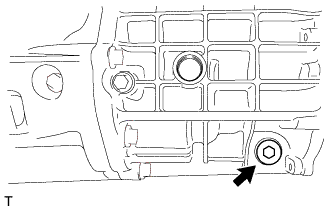 |
Remove the manual transmission drain plug and gasket.
| 3. REMOVE RELEASE FORK SUPPORT |
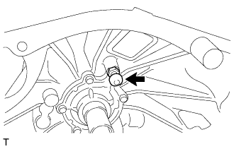 |
Using a 19 mm deep socket wrench, remove the release fork support from the clutch housing.
| 4. REMOVE BACK-UP LIGHT SWITCH ASSEMBLY |
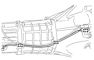 |
Disengage the 3 clamps.
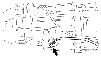 |
Using a 19 mm union nut wrench, remove the back-up light switch assembly and gasket.
| 5. REMOVE NEUTRAL POSITION SWITCH ASSEMBLY |
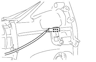 |
Disengage the clamp.
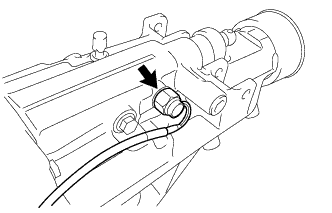 |
Using a 19 mm union nut wrench, remove the neutral position switch assembly and gasket.
| 6. REMOVE WIRE HARNESS CLAMP BRACKET |
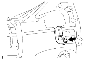 |
Remove the bolt and wire harness clamp bracket.
| 7. REMOVE LOCK BALL PIN |
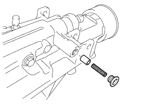 |
Using a 10 mm hexagon socket wrench, remove the head straight screw plug, compression spring and lock ball pin.
| 8. REMOVE HOLDER |
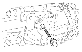 |
Using a 27 mm deep socket wrench, remove the holder, compression spring and lock ball pin.
| 9. REMOVE TRANSMISSION EXTENSION HOUSING SUB-ASSEMBLY |
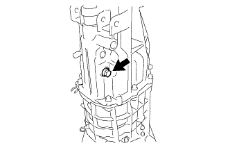 |
Remove the bolt.
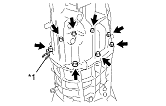 |
Remove the 8 bolts and clamp.
| *1 | Clamp |
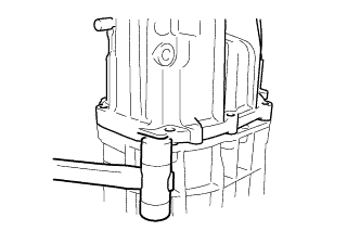 |
Using a plastic hammer, remove the transmission extension housing sub-assembly.
| 10. REMOVE EXTENSION HOUSING REAR OIL SEAL |
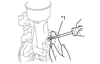 |
Using a screwdriver with its tip wrapped with protective tape, remove the extension housing rear oil seal.
| *1 | Protective Tape |
| 11. REMOVE EXTENSION HOUSING DUST DEFLECTOR |
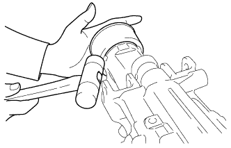 |
Using a plastic hammer, remove the extension housing dust deflector.
| 12. REMOVE TRANSMISSION EXTENSION HOUSING OIL SEAL |
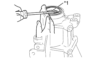 |
Using a screwdriver with its tip wrapped with protective tape, remove the transmission extension housing oil seal.
| *1 | Protective Tape |
| 13. REMOVE NO. 2 EXTENSION HOUSING OIL RECEIVER PIPE |
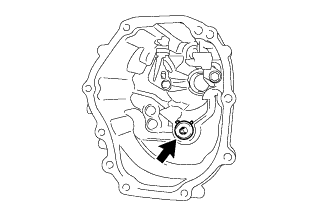 |
Remove the No. 2 extension housing oil receiver pipe.
| 14. REMOVE NO. 1 EXTENSION HOUSING OIL RECEIVER PIPE |
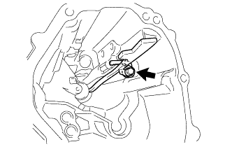 |
Remove the bolt, No. 1 extension housing oil receiver pipe and stopper plate.
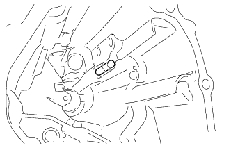 |
Remove the straight pin.
| 15. REMOVE SHIFT SHAFT |
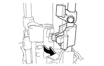 |
Slide and remove the shift shaft and No. 1 shift inter lock block.
| 16. REMOVE NO. 1 SHIFT INTER LOCK BLOCK |
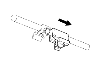 |
Remove the No. 1 shift inter lock block from the shift shaft.
| 17. REMOVE FRONT SHIFT INNER LEVER |
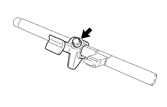 |
Remove the bolt and front shift inner lever from the shift shaft.
| 18. REMOVE HEAD STRAIGHT SCREW PLUG |
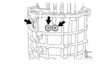 |
Using a T40 "TORX" socket wrench, remove 3 head straight screw plugs.
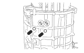 |
Using a magnet hand, remove the 2 compression springs and 2 balls.
| 19. REMOVE SHIFT ARM |
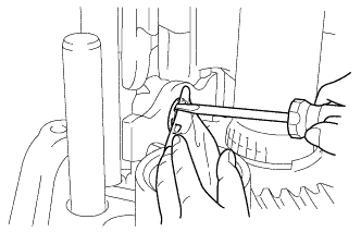 |
Using a screwdriver, remove the E-ring.
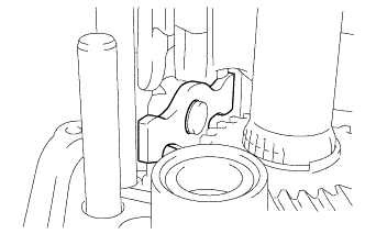 |
Remove the shift arm.
| 20. REMOVE NO. 3 GEAR SHIFT FORK SHAFT |
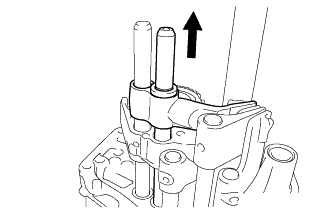 |
Remove the No. 3 gear shift fork shaft and 5th shift head together.
Remove the ball from the 5th shift head.
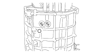 |
Using a magnetic hand, remove the ball.
| 21. REMOVE 5TH SHIFT HEAD |
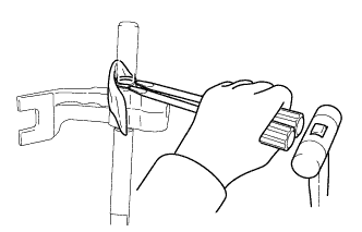 |
Using 2 screwdrivers and a plastic hammer, remove the shaft snap ring.
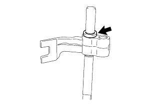 |
Remove the washer.
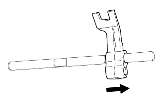 |
Remove the 5th shift head, compression spring and ball.
| 22. INSPECT COUNTER SHAFT 6TH GEAR THRUST CLEARANCE |
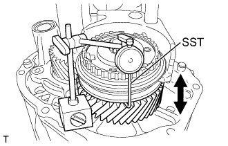 |
Using SST and a dial indicator, measure the thrust clearance.
| 23. INSPECT COUNTER SHAFT 6TH GEAR RADIAL CLEARANCE |
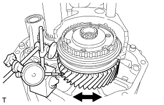 |
Using a dial indicator, measure the radial clearance.
| 24. REMOVE NO. 4 TRANSMISSION CLUTCH HUB |
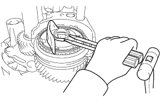 |
Using 2 screwdrivers and a plastic hammer, remove the shaft snap ring.
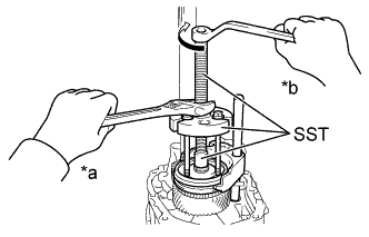 |
Using SST and 3 bolts, remove the No. 4 transmission clutch hub, No.4 transmission hub sleeve, No. 4 gear shift fork and No. 2 gear shift fork shaft all together.
| *a | Hold |
| *b | Turn |
| 25. REMOVE NO. 4 GEAR SHIFT FORK |
for Pin:
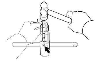 |
Using a 5 mm pin punch and hammer, remove the slotted spring pin.
Remove the No. 4 gear shift fork from the No. 2 gear shift fork shaft.
for Bolt:
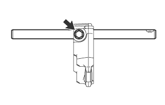 |
Remove the bolt and No. 4 gear shift fork from the No. 2 gear shift fork shaft.
| 26. REMOVE NO. 4 TRANSMISSION HUB SLEEVE |
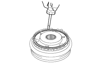 |
Using a screwdriver, remove the hole snap ring.
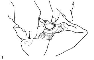 |
Remove the No. 4 transmission hub sleeve, and then remove the 3 No. 1 synchromesh shifting keys, 3 No. 1 synchromesh shifting key springs and 3 balls from the No. 4 transmission clutch hub.
| 27. REMOVE NO. 2 SYNCHRONIZER RING |
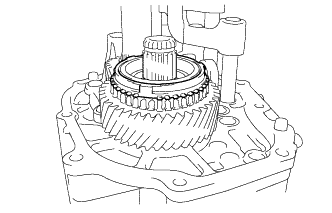 |
Remove the No. 2 synchronizer ring.
| 28. REMOVE COUNTER SHAFT 6TH GEAR |
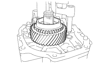 |
Remove the counter shaft 6th gear.
| 29. REMOVE NEEDLE ROLLER BEARING |
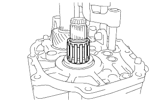 |
Remove the needle roller bearing.
| 30. REMOVE 6TH GEAR THRUST WASHER |
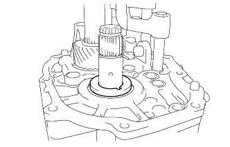 |
Remove the 6th gear thrust washer.
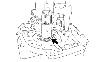 |
Remove the straight pin.
| 31. REMOVE NO. 2 GEAR SHIFT HEAD |
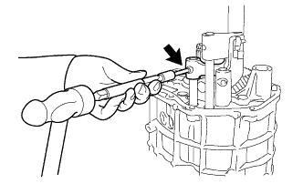 |
Using a 5 mm pin punch and hammer, remove the slotted spring pin.
Remove the No. 2 gear shift head from the No. 2 gear shift fork shaft.
| 32. REMOVE NO. 1 GEAR SHIFT HEAD |
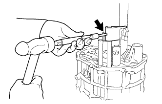 |
Using a 5 mm pin punch and a hammer, remove the slotted spring pin.
Remove the No. 1 gear shift head from the No. 1 gear shift fork shaft.
| 33. REMOVE NO. 3 GEAR SHIFT HEAD |
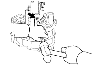 |
Using a 5 mm pin punch and a hammer, remove the slotted spring pin.
Remove the No. 3 gear shift head from the No. 3 gear shift fork shaft.
| 34. REMOVE REAR BEARING RETAINER |
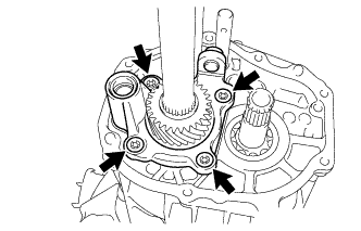 |
Using a T45 "TORX" socket wrench, remove the 4 bolts and rear bearing retainer.
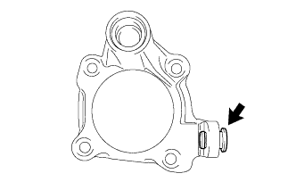 |
Remove the shift arm pivot.
| 35. REMOVE TRANSMISSION CASE |
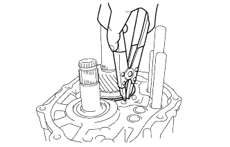 |
Using a snap ring expander, remove the shaft snap ring.
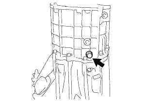 |
Remove the bolt that retains the reverse idler gear shaft, and the gasket (transmission case side)
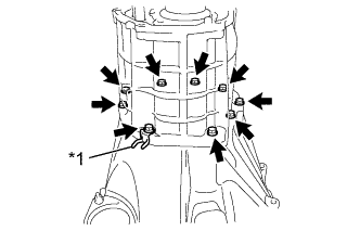 |
Remove the 9 bolts and clamp.
| *1 | Clamp |
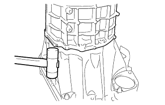 |
Using a plastic hammer, remove the transmission case.
| 36. REMOVE OIL RECEIVER PIPE |
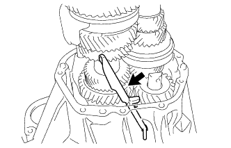 |
Remove the oil receiver pipe.
| 37. REMOVE FRONT BEARING RETAINER |
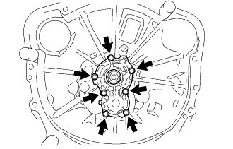 |
Remove 7 bolts and front bearing retainer.
| 38. REMOVE TRANSMISSION FRONT BEARING RETAINER OIL SEAL |
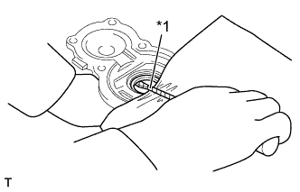 |
Using a screwdriver with its tip wrapped with protective tape, remove the transmission front bearing retainer oil seal.
| *1 | Protective Tape |
| 39. REMOVE COUNTER SHAFT |
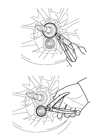 |
Using a snap ring expander, remove the 2 shaft snap rings.
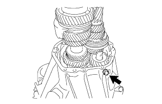 |
Remove the bolt and gasket to free the reverse idler gear and reverse idler gear shaft. (Clutch housing side)
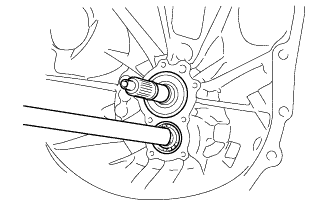 |
Using a hammer handle edge, tap to remove the input shaft, output shaft, counter shaft, reverse idler gear, reverse idler gear shaft, No. 1 gear shift fork shaft, No. 2 gear shift fork shaft and No. 3 gear shift fork shaft all together from the clutch housing side.
| 40. REMOVE NO. 2 GEAR SHIFT FORK SHAFT |
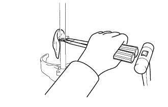 |
Using 2 screwdrivers and a plastic hammer, remove the shaft snap ring.
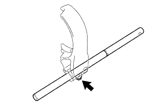 |
Remove the bolt and No. 2 gear shift fork shaft.
| 41. REMOVE NO. 1 GEAR SHIFT FORK SHAFT |
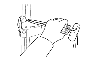 |
Using 2 screwdrivers and a plastic hammer, remove the shaft snap ring.
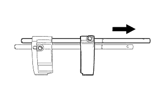 |
Remove the No. 1 gear shift fork shaft and No.1 gear shift fork together.
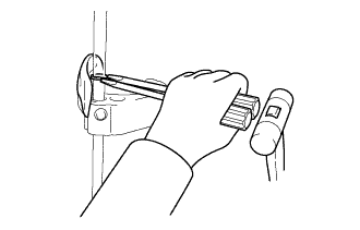 |
Using 2 screwdrivers and a plastic hammer, remove the shaft snap ring.
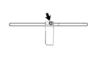 |
Remove the bolt and No. 1 gear shift fork shaft.
| 42. REMOVE NO. 3 GEAR SHIFT FORK SHAFT |
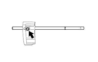 |
Remove the bolt and No. 3 gear shift fork shaft.
| 43. REMOVE INPUT SHAFT |
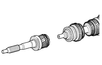 |
Remove the input shaft from the output shaft.
| 44. INSPECT REVERSE IDLER GEAR RADIAL CLEARANCE |
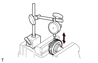 |
Use a vice to secure the reverse idler gear, and then use a dial indicator to measure the radial clearance.
| 45. REMOVE REVERSE IDLER GEAR SHAFT |
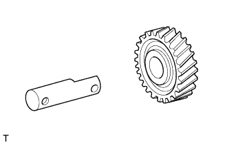 |
Remove the reverse idler gear shaft from the reverse idler gear.