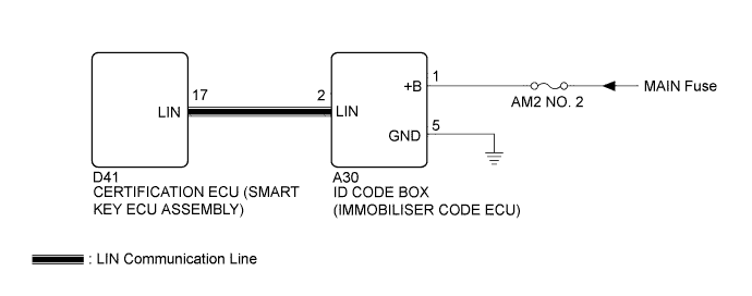
DTC B2789 No Response from ID BOX |
| DTC No. | DTC Detection Condition | Trouble Area |
| B2789 | No communication between the certification ECU (smart key ECU assembly) and the ID code box (immobiliser code ECU) for more than 10 seconds |
|
| 1.CLEAR DTC |
Clear the DTC (Click here).
| NEXT | |
 |
| 2.CHECK DTC |
Check for DTC (Click here).
| Result | Proceed to |
| DTC B2789 is output | A |
| DTC B2789 and B2785 is output | B |
|
| ||||
| A | |
|
| 3.CHECK HARNESS AND CONNECTOR (CERTIFICATION ECU (SMART KEY ECU ASSEMBLY) - ID CODE BOX (IMMOBILISER CODE ECU)) |
Disconnect the D41 certification ECU (smart key ECU assembly) connector.
Disconnect the A30 ID code box (immobiliser code ECU) connector.
Measure the resistance according to the value(s) in the table below.
| Tester Connection | Condition | Specified Condition |
| D41-17 (LIN) - A30-2 (LIN) | Always | Below 1 Ω |
| Tester Connection | Condition | Specified Condition |
| D41-17 (LIN) or A30-2 (LIN) - Body ground | Always | 10 kΩ or higher |
|
| ||||
| OK | |
|
| 4.CHECK HARNESS AND CONNECTOR (POWER SOURCE CIRCUIT) |
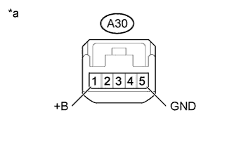 |
Measure the voltage according to the value(s) in the table below.
| Tester Connection | Condition | Specified Condition |
| A30-1 (+B) - Body ground | Always | 11 to 14 V |
Measure the resistance according to the value(s) in the table below.
| Tester Connection | Condition | Specified Condition |
| A30-5 (GND) - Body ground | Always | Below 1 Ω |
| *a | Front view of wire harness connector (to ID Code Box (Immobiliser Code ECU)) |
|
| ||||
| OK | |
|
| 5.REPLACE ID CODE BOX (IMMOBILISER CODE ECU) |
Replace the ID code box (immobiliser code ECU).
| NEXT | |
|
| 6.CHECK FOR DTC |
Clear the DTC (Click here).
Recheck for DTC.
| Result | Proceed to |
| B2789 is not output | A |
| B2789 is output | B |
|
| ||||
| A | ||
 | ||
| ||
