 |
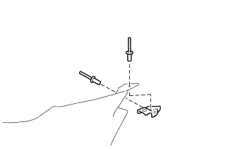
Using an air riveter or a hand riveter, install the front bumper side retainer LH with 2 new rivets.
FRONT BUMPER > REASSEMBLY |
| 1. INSTALL FRONT BUMPER SIDE RETAINER LH |
|
Using an air riveter or a hand riveter, install the front bumper side retainer LH with 2 new rivets.
| 2. INSTALL FRONT BUMPER SIDE RETAINER RH |
| 3. INSTALL FRONT BUMPER HOLE COVER |
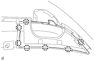 |
Engage the 7 claws to install the front bumper hole cover (lower side).
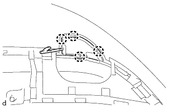 |
Engage the 4 claws to install the front bumper hole cover (upper side).
| 4. INSTALL FOG LIGHT COVER LH |
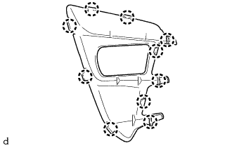 |
Engage the 10 claws to install the fog light cover LH.
| 5. INSTALL FOG LIGHT COVER RH |
| 6. INSTALL FOG LIGHT ASSEMBLY LH (w/ Fog Light) |
Cover the fog light or disconnect the connector of the fog light on the opposite side to prevent light from the fog light that is not being inspected from affecting the fog light aiming inspection.
Start the engine.
Turn on the fog lights and check if the upper edge of the hot zone for each fog light matches the upper edge as shown in the illustration (except China).
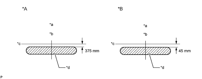
| *A | Aligning distance 25 m (82 ft.) | *B | Aligning distance 3 m (9.84 ft.) |
| *a | V RH Line | *b | V LH Line |
| *c | H Line | *d | Hot Zone |
Turn on the fog lights and check if the upper edge of the hot zone for each fog light matches the upper edge as shown in the illustration (for China).
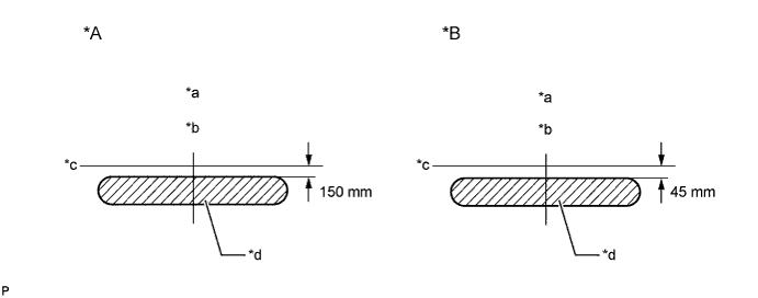
| *A | Aligning distance 10 m (32.8 ft.) | *B | Aligning distance 3 m (9.84 ft.) |
| *a | V RH Line | *b | V LH Line |
| *c | H Line | *d | Hot Zone |
| 7. INSTALL FOG LIGHT ASSEMBLY RH (w/ Fog Light) |
| 8. INSTALL FRONT BUMPER HOLE COVER LH |
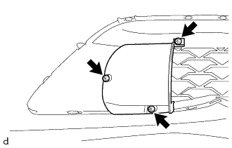 |
Install the front bumper hole cover LH with the 3 screws.
| 9. INSTALL FRONT BUMPER HOLE COVER RH |
| 10. INSTALL NO. 1 LOWER RADIATOR GRILLE |
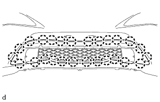 |
Engage the 26 claws to install the No. 1 lower radiator grille.
| 11. INSTALL RADIATOR GRILLE (OR FRONT PANEL) EMBLEM |
Clean the attachment surface.
Using an infrared light, heat the double-sided adhesive tape remaining on the front bumper cover.
| Item | Temperature |
| Front Bumper Cover | 40 to 60°C (104 to 140°F) |
Using a piece of cloth, rub the remaining double-sided tape off the front bumper cover while it is hot from the infrared light.
Using a non-residue solvent, clean the attachment surface.
Using an infrared light, heat the radiator grille emblem installation surface of the front bumper cover and new radiator grille emblem.
| Item | Temperature |
| Front Bumper Cover | 40 to 60°C (104 to 140°F) |
| Radiator Grille Emblem | 20 to 30°C (68 to 86°F) |
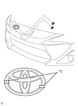 |
Insert the 2 pins into the front bumper cover and install a new radiator grille emblem with the new 2 push nuts.
| *1 | Location Pin |
| 12. INSTALL FRONT BUMPER REINFORCEMENT SUB-ASSEMBLY |
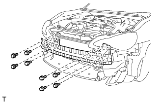 |
Install the front bumper reinforcement sub-assembly with the 8 bolts.
| 13. INSTALL LOW PITCHED HORN ASSEMBLY (for China) |
Install the bolt and low pitched horn assembly with horn bracket sub-assembly.
Connect the connector.
| 14. INSTALL HIGH PITCHED HORN ASSEMBLY (except China) |
Install the bolt and high pitched horn assembly with horn bracket sub-assembly.
Connect the connector.
| 15. INSTALL RADIATOR COVER PLATE |
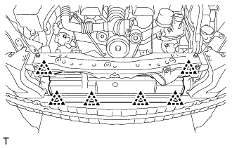 |
Install the radiator cover plate with the 6 clips.
| 16. INSTALL FRONT BUMPER ENERGY ABSORBER |
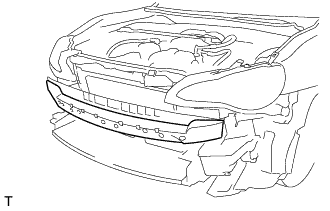 |
Install the front bumper energy absorber.
| 17. INSTALL FRONT BUMPER STAY BRACKET |
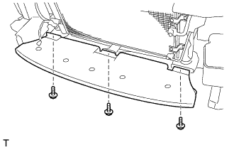 |
Install the front bumper stay bracket with the 3 bolts.
| 18. INSTALL FRONT LOWER BUMPER COVER |
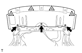 |
Install the front lower bumper cover with the 3 bolts.
Install the 4 clips.
| 19. INSTALL FRONT BUMPER REINFORCEMENT PLATE LH |
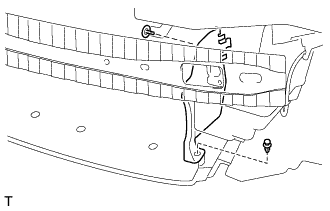 |
Install the front bumper reinforcement plate LH with the 2 clips.
| 20. INSTALL FRONT BUMPER REINFORCEMENT PLATE RH |
| 21. INSTALL NO. 2 FRONT BUMPER SIDE SUPPORT LH |
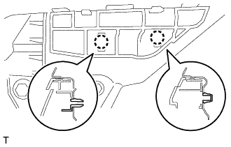 |
Engage the 2 claws.
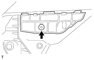 |
Install the No. 2 front bumper side support LH with the screw.
| 22. INSTALL NO. 2 FRONT BUMPER SIDE SUPPORT RH |
| 23. INSTALL LICENSE PLATE BRACKET |
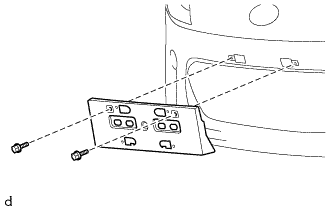 |
Type A
Install the license plate bracket with the 2 bolts.
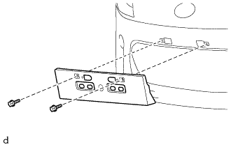 |
Type B
Install the license plate bracket with the 2 bolts.
| 24. INSTALL HOOD TO FRONT END PANEL SEAL |
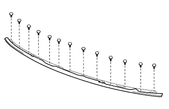 |
Install the hood to front end panel seal to the front bumper upper retainer with the 13 clips.