Home › Engine / Hybrid System › FA20 EMISSION CONTROL › CANISTER

CANISTER > INSPECTION

for Preparation Click here


1. INSPECT CHARCOAL CANISTER ASSEMBLY (for Metal Type)

NOTICE:
When applying vacuum, the needle may waver but, as long as the needle returns to its initial position immediately, it is not a malfunction.

  1. Visually check the charcoal canister assembly for cracks or damage.
    If cracks or damage is found, replace the charcoal canister assembly.


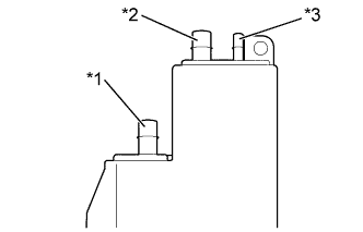
  1. Check the air flow.


      A282933E01
    1. Using a vacuum pump, check the air flow according to the procedures below.
      Text in Illustration 
      *1
      Port A
      *2
      Port B
      *3
      Port C

      OK:
      Measurement Condition
      Specified Condition
      Ports B and C closed, and vacuum applied to port A (2 kPa (15 mmHg, 0.590 in.Hg))
      No air leaks
      Port C closed, and vacuum applied to port A (2 kPa (15 mmHg, 0.590 in.Hg))
      Air flows from port B
      Port C closed and air blown into port A (5 kPa (0.1 kgf/cm2, 0.725 psi))
      Air flows from port B
      Air blown into port A (5 kPa (0.1 kgf/cm2, 0.725 psi))
      Air flows from ports B and C

      If the result is not as specified, replace the charcoal canister assembly.


2. INSPECT CHARCOAL CANISTER ASSEMBLY (for Clamp Type)

NOTICE:
When applying vacuum, the needle may waver but, as long as the needle returns to its initial position immediately, it is not a malfunction.

  1. Visually check the charcoal canister assembly for cracks or damage.
    If cracks or damage is found, replace the charcoal canister assembly.


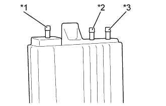
  1. Check the air flow.


      A285064E01
    1. Using a vacuum pump, check the air flow according to the procedures below.
      Text in Illustration 
      *1
      Port A
      *2
      Port B
      *3
      Port C

      OK:
      Measurement Condition
      Specified Condition
      Ports B and C closed, and vacuum applied to port A (2 kPa (15 mmHg, 0.590 in.Hg))
      No air leaks
      Port C closed, and vacuum applied to port A (2 kPa (15 mmHg, 0.590 in.Hg))
      Air flows from port B
      Port C closed and air blown into port A (5 kPa (0.1 kgf/cm2, 0.725 psi))
      Air flows from port B
      Air blown into port A (5 kPa (0.1 kgf/cm2, 0.725 psi))
      Air flows from ports B and C

      If the result is not as specified, replace the charcoal canister assembly.


3. INSPECT CANISTER PUMP MODULE (for Metal Type)


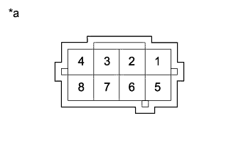
    A281853E01
  1. Measure the resistance according to the value in the table below.

    Standard Resistance:
    Tester Connection
    Condition
    Specified Condition
    1 - 5
    20°C (68°F)
    25 to 30 Ω
    1 - 5
    60°C (140°F)
    27 to 35 Ω

    Text in Illustration 
    *a
    Component without harness connected
    (Canister Pump Module)


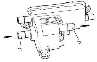
  1. Check the operation of the check valve.


      A281854E01
    1. Install a clean hose to the purge valve.

    2. Check that air flows from port A to port B.
      Text in Illustration 
      *1
      Port A
      *2
      Port B


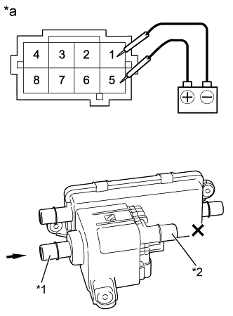
    3. A281855E02
    4. Connect the positive (+) lead of the battery to terminal 5 and the negative (-) lead to terminal 1.

    5. Check that air does not flow from port A to port B.
      Text in Illustration 
      *1
      Port A
      *2
      Port B
      *a
      Component without harness connected
      (Canister Pump Module)


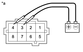
    6. A281856E01
    7. Connect the positive (+) lead of the battery to terminal 3 and the negative (-) lead to terminal 4.
      Text in Illustration 
      *a
      Component without harness connected
      (Canister Pump Module)

    8. Check that the vacuum pump operates.

      NOTICE:
      Do not operate vacuum pump for 5 minutes or more.


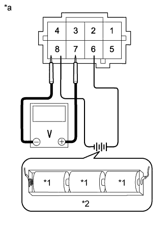
    9. A281857E01
    10. Connect the positive (+) lead of the battery to terminal 6 and the negative (-) lead to terminal 8.
      Text in Illustration 
      *1
      1.5 V
      *2
      4.8 to 5.2 V
      *a
      Component without harness connected
      (Canister Pump Module)

    11. Measure the voltage according to the value in the table below.

      Standard Voltage:
      Tester Connection
      Condition
      Specified Condition
      7 - 8
      25°C (77°F)
      3.5 V


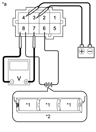
    12. A281858E02
    13. Connect the positive (+) lead of the battery to terminal 6 and the negative (-) lead to terminal 8.
      Text in Illustration 
      *1
      1.5 V
      *2
      4.8 to 5.2 V
      *a
      Component without harness connected
      (Canister Pump Module)

    14. Connect the positive (+) lead of the battery to terminal 3 and the negative (-) lead to terminal 4. Check that the voltage drops slightly from 3.5 volts.