 |
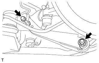
Remove the 2 bolts, 2 nuts and the rear No. 1 suspension arm assembly LH.
TOE CONTROL LINK > REMOVAL |
| 1. REMOVE REAR WHEEL |
| 2. REMOVE REAR NO. 1 SUSPENSION ARM ASSEMBLY LH |
|
Remove the 2 bolts, 2 nuts and the rear No. 1 suspension arm assembly LH.
| 3. REMOVE TOE CONTROL LINK SUB-ASSEMBLY LH |
Remove the snap pin.
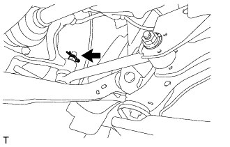 |
Remove the nut on the rear axle carrier side.
Install SST (2 pieces of spacer B) to the threaded section of the t toe control link sub-assembly LH.
Using SST (ball join puller), separate the toe control link sub-assembly LH from the rear axle carrier LH.
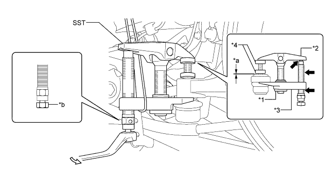
| *1 | Nut | *2 | Body |
| *3 | Claw | *4 | SST (Spacer B) |
| *a | 1 mm (0.039 in.) | *b | Place wrench here |
 | Molybdenum grease |  | Turning direction |
Put matchmarks on the rear No. 2 suspension toe adjust plate and the rear suspension member.
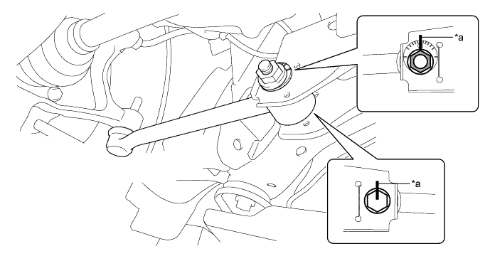
| *a | Matchmark | - | - |
Remove the nut, toe adjust cam, rear No. 2 suspension toe adjust plate and the toe control link sub-assembly.