 |
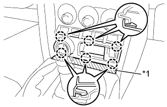
Apply protective tape to the area shown in the illustration.
| *1 | Protective Tape |
FRONT CONSOLE BOX > REMOVAL |
| 1. REMOVE FRONT CONSOLE BOX COVER (w/ Entry and Start System) |
Move the shift lever to N.
|
Apply protective tape to the area shown in the illustration.
| *1 | Protective Tape |
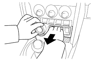 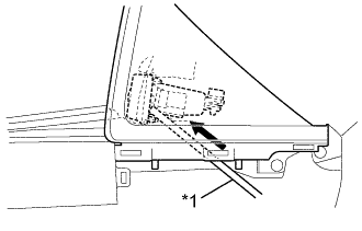 |
Disengage the 6 claws and remove the front console box cover.
| *1 | Bar |
Disconnect each connector.
| 2. REMOVE PUSH START SWITCH (w/ Entry and Start System) |
Disconnect the engine switch connector.
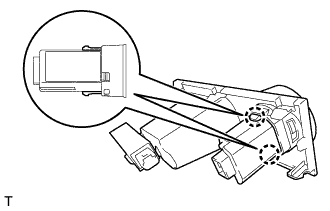 |
Disengage the 2 claws and remove the engine switch.
| 3. REMOVE INDOOR ELECTRICAL KEY OSCILLATOR (w/ Entry and Start System) |
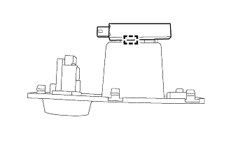 |
Disengage the clamp and remove the indoor electrical key oscillator.
| 4. REMOVE FRONT CONSOLE BOX COVER (w/o Entry and Start System) |
Move the shift lever to N.
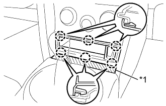 |
Apply protective tape to the area shown in the illustration.
| *1 | Protective Tape |
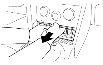 |
Disengage the 6 claws and remove the front console box cover.
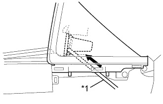 |
| *1 | Bar |
| 5. REMOVE NO. 1 STEREO JACK ADAPTER ASSEMBLY (w/ Stereo Jack Adapter) |
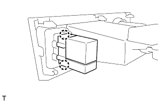 |
Disengage the 2 claws and remove the No. 1 stereo jack adapter assembly.
| 6. REMOVE SHIFT LEVER KNOB SUB-ASSEMBLY (for Automatic Transmission) |
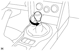 |
Turn the knob counterclockwise and remove the shift lever knob sub-assembly.
| 7. REMOVE UPPER CONSOLE PANEL SUB-ASSEMBLY (for Automatic Transmission) |
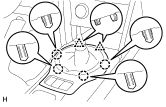 |
Disengage the 2 clips and 4 claws.
Disconnect each connector and remove the upper console panel sub-assembly.
| 8. REMOVE SHIFT POSITION INDICATOR (for Automatic Transmission) |
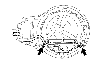 |
Remove the 2 screws.
Disengage the clamp to remove the shift position indicator.
| 9. REMOVE SHIFTING HOLE COVER SUB-ASSEMBLY (for Automatic Transmission) |
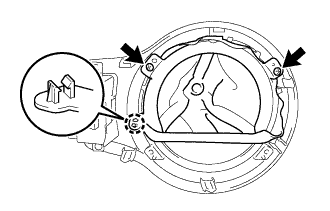 |
Remove the 2 screws.
Disengage the claw to remove the shifting hole cover sub-assembly.
| 10. REMOVE PATTERN SELECT SWITCH ASSEMBLY (for Automatic Transmission) |
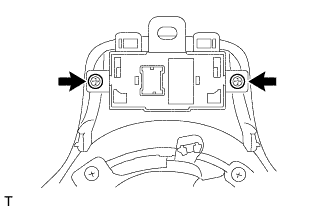 |
Remove the 2 screws and the pattern select switch assembly.
| 11. REMOVE SHIFT LEVER KNOB SUB-ASSEMBLY (for Manual Transmission) |
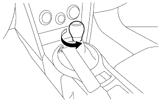 |
Turn the knob counterclockwise and remove the shift lever knob sub-assembly.
| 12. REMOVE UPPER CONSOLE PANEL SUB-ASSEMBLY (for Manual Transmission) |
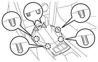 |
Disengage the 2 clips and 4 claws.
Disconnect each connector and remove the upper console panel sub-assembly.
| 13. REMOVE SHIFTING HOLE COVER SUB-ASSEMBLY (for Manual Transmission) |
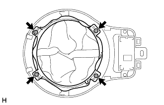 |
Remove the 4 screws and the shifting hole cover sub-assembly.
| 14. REMOVE PATTERN SELECT SWITCH ASSEMBLY (for Manual Transmission) |
Disconnect the pattern select switch assembly connector.
Disconnect the pattern select switch assembly connector clamp. (for Automatic Transmission)
|
Remove the 2 screws and the pattern select switch assembly from the shifting hole cover sub-assembly.
| 15. REMOVE NO. 1 ASH RECEPTACLE SUB-ASSEMBLY (w/ Ashtray) |
Remove the No. 1 ash receptacle sub-assembly.
| 16. REMOVE INSTRUMENT PANEL CUP HOLDER |
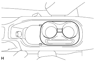 |
Remove the instrument panel cup holder.
| 17. REMOVE CUP HOLDER CUSHION |
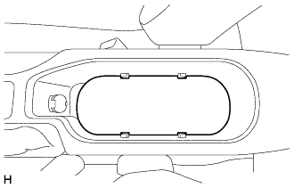 |
Remove the cup holder cushion.
| 18. REMOVE PARKING BRAKE HOLE COVER |
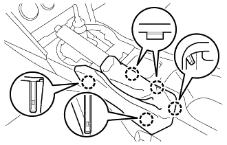 |
Disengage the 5 claws to remove the parking brake hole cover.
| 19. REMOVE INSTRUMENT PANEL FINISH PANEL END LH |
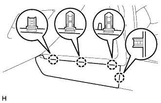 |
Disengage the 4 claws to remove the instrument panel finish panel end LH.
| 20. REMOVE INSTRUMENT PANEL FINISH PANEL END RH |
| 21. REMOVE CONSOLE BOX ASSEMBLY |
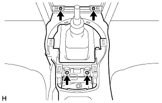 |
Remove the 4 screws.
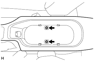 |
Remove the 2 bolts.
Disconnect each connector and remove the console box assembly.