UPPER INSTRUMENT PANEL > REMOVAL |
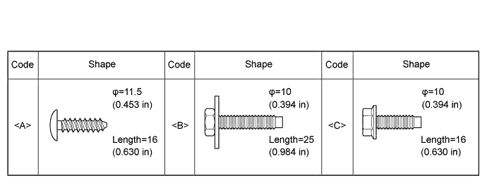
| 1. TABLE OF BOLT, SCREW AND NUT |
All bolts, screws and nuts relevant to installing and removing the instrument panel are shown along with their alphabetical code in the table.
| 2. PRECAUTION |
| 3. DISCONNECT CABLE FROM NEGATIVE BATTERY TERMINAL |
| 4. REMOVE LOWER INSTRUMENT PANEL SUB-ASSEMBLY |
| 5. REMOVE NO. 2 INSTRUMENT PANEL SPEAKER PANEL SUB-ASSEMBLY |
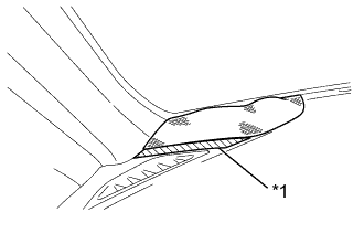 |
Apply protective tape to the area shown in the illustration.
| *1 | Protective Tape |
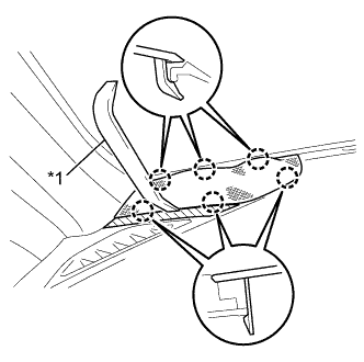 |
Using a moulding remover, disengage the 6 claws and remove the No. 2 instrument panel speaker panel sub-assembly.
| *1 | Moulding Remover |
Disconnect the connector.
| 6. REMOVE FRONT NO. 2 SPEAKER ASSEMBLY (for 6 Speakers) |
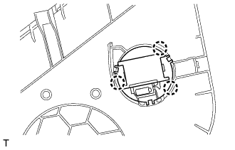 |
Disengage the 3 claws and remove the front No. 2 speaker assembly from the No. 2 instrument speaker panel sub-assembly.
| 7. REMOVE NO. 1 INSTRUMENT PANEL SPEAKER PANEL SUB-ASSEMBLY |
| 8. REMOVE FRONT NO. 2 SPEAKER ASSEMBLY (for 6 Speakers) |
|
Disengage the 3 claws and remove the front No. 2 speaker assembly from the No. 2 instrument speaker panel sub-assembly.
| 9. REMOVE FRONT PILLAR GARNISH LH |
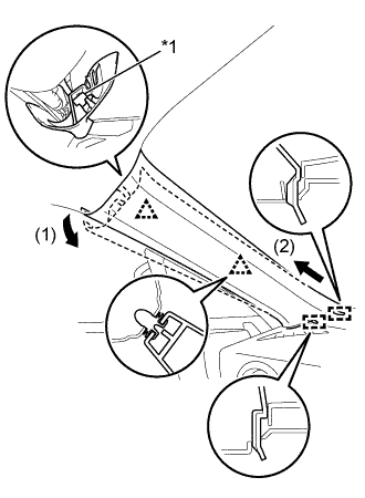 |
Pull the upper part of the front pillar garnish LH in the direction of the arrow (1), and disengage the 2 clips and the front pillar garnish clip.
| *1 | Front Pillar Garnish Clip |
Pull the front pillar garnish LH in the direction of the arrow (2) and disengage the 2 guides.
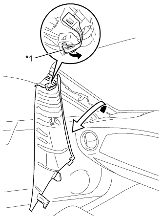 |
Turn the front pillar garnish LH in the direction of the arrow.
Disengage the tip of the front pillar garnish clip and remove the front pillar garnish LH.
| *1 | Front Pillar Garnish Clip |
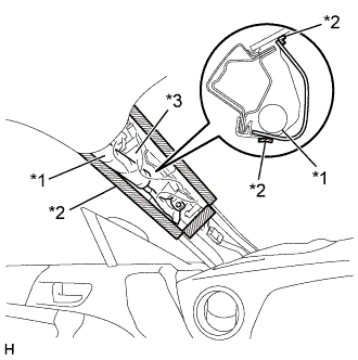 |
Protect the curtain shield airbag assembly (w/curtain shield airbag).
| *1 | Curtain Shield Airbag Assembly |
| *2 | Adhesive Tape |
| *3 | Protective Cover |
Cover the airbag with a piece of cloth or nylon and secure the edges of the cover with tape as shown in the illustration.
| 10. REMOVE FRONT PILLAR GARNISH RH |
| 11. REMOVE COMBINATION METER ASSEMBLY |
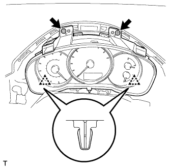 |
Remove the 2 screws.
Disengage the 2 clips.
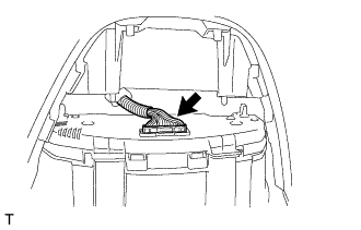 |
Disconnect the connector and remove the combination meter assembly.
| 12. REMOVE INSTRUMENT PANEL ORNAMENT |
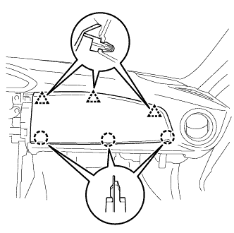 |
Disengage the 3 clips and 3 claws to remove the instrument panel ornament.
| 13. REMOVE AUTOMATIC LIGHT CONTROL SENSOR (w/ Automatic Light Control System) |
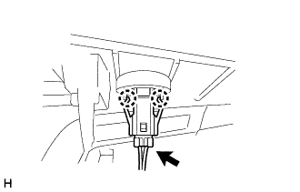 |
Disconnect the connector.
Disengage the 2 claws and remove the automatic light control sensor.
| 14. REMOVE INSTRUMENT PANEL PASSENGER AIRBAG ASSEMBLY |
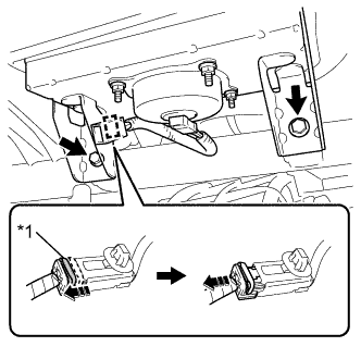 |
Disengage the clamp.
Slide the slider and disconnect the passenger airbag connector.
| *1 | Slider |
Remove the 2 bolts and the instrument panel passenger airbag assembly.
| 15. REMOVE INSTRUMENT PANEL SUB-ASSEMBLY |
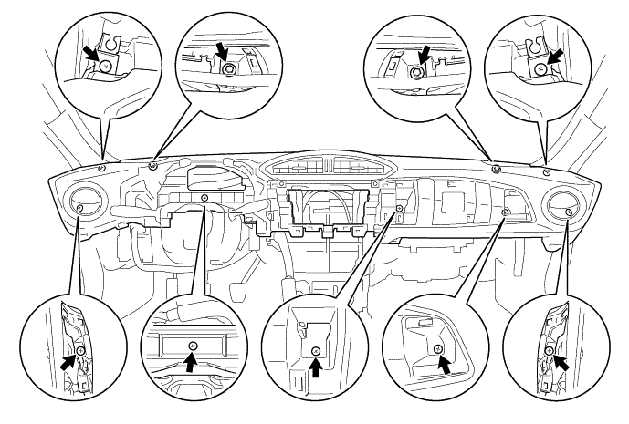
Remove the 2 bolts and 7 screws to remove the instrument panel sub-assembly.