 |
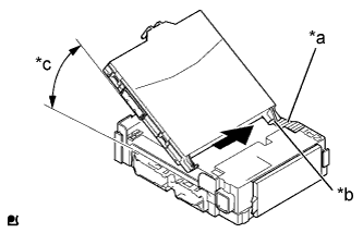
Make the network gateway ECU guide to contact the housing side wall.
- HINT:
- The angle between the junction block and the network gateway ECU guide should be 20° or more.
| *a | Housing Side Wall |
| *b | Guide |
| *c | 20° or more |
MAIN BODY ECU > INSTALLATION |
| 1. INSTALL NETWORK GATEWAY ECU |
|
Make the network gateway ECU guide to contact the housing side wall.
| *a | Housing Side Wall |
| *b | Guide |
| *c | 20° or more |
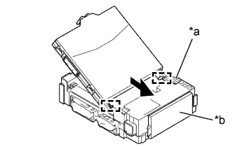 |
While aligning the guide with the housing side wall, slide the network gateway ECU toward the fuse area of the instrument panel junction block assembly and engage the 2 guides.
| *a | Hosing Side Wall |
| *b | Fuse Area |
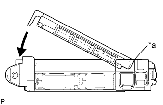 |
Slide the network gateway ECU until it contacts the A surface.
Rotate the network gateway ECU while holding it against the instrument panel junction block assembly surface (axis of rotation).
| *a | A surface |
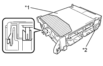 |
Rotate the network gateway ECU until it engages with the lock to install it.
| *1 | Network Gateway ECU |
| *2 | Instrument Panel Junction Block Assembly |
 | Push Area |
| 2. INSTALL INSTRUMENT PANEL JUNCTION BLOCK ASSEMBLY |
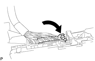 |
Connect the connector as shown in the illustration.
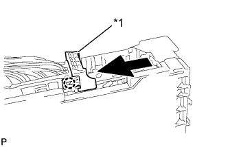 |
Slide the lever as indicated by the arrow shown in the illustration.
| *1 | Lever |
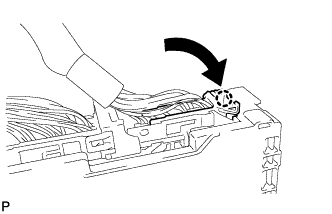 |
Connect the connector indicated as shown in the illustration.
Install the instrument panel junction block assembly with the bolt and the nut.
Connect 6 connectors to the instrument panel junction block assembly.
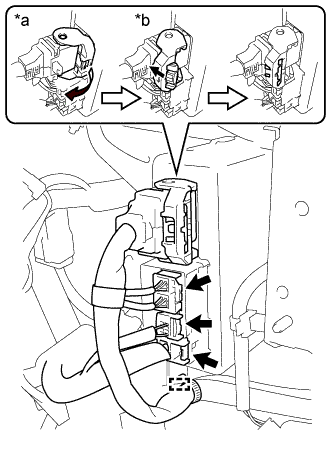 |
Connect the 3 connectors to the power steering ECU assembly.
Connect the connector to the power steering ECU assembly.
As shown in the illustration, return the lock lever to its original position to connect the connector and securely push in the lock of the lock lever.
| *a | Return the lock lever |
| *b | Push the lock |
| 3. INSTALL NO. 1 INSTRUMENT PANEL UNDER COVER SUB-ASSEMBLY (w/o Knee Airbag) |
Connect each connector.
 |
for Automatic Air Conditioning System for RHD:
Connect the connector.
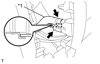
Engage the guide and connect the aspirator hose.
| *1 | Aspirator Hose |
Engage the 4 claws.
Engage the 4 clips to install the No. 1 instrument panel under cover sub-assembly.
Install the 2 screws.
| 4. INSTALL NO. 1 INSTRUMENT PANEL UNDER COVER SUB-ASSEMBLY (w/ Knee Airbag) |
Connect each connector.
Engage the 2 claws.
Engage the 6 clips to install the No. 1 instrument panel under cover sub-assembly.
Install the screw.
| 5. INSTALL INSTRUMENT SIDE PANEL LH |