 |
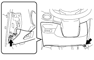
Remove the 2 screws.
MAIN BODY ECU > REMOVAL |
| 1. REMOVE INSTRUMENT SIDE PANEL LH |
| 2. REMOVE NO. 1 INSTRUMENT PANEL UNDER COVER SUB-ASSEMBLY (w/o Knee Airbag) |
|
Remove the 2 screws.
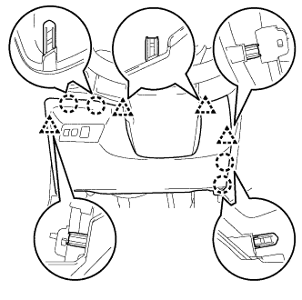 |
Disengage the 4 clips.
Disengage the 4 claws and separate the No. 1 instrument panel under cover sub-assembly.
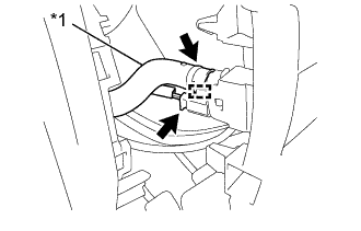 |
w/ Automatic Air Conditioning System for RHD:
Disengage the guide and disconnect the aspirator hose.
Disconnect the connector.
Disconnect each connector and remove the No. 1 instrument panel under cover sub-assembly.
| *1 | Aspirator Hose |
| 3. REMOVE NO. 1 INSTRUMENT PANEL UNDER COVER SUB-ASSEMBLY (w/ Knee Airbag) |
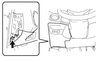 |
Remove the screw.
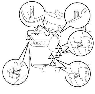 |
Disengage the 6 clips.
Disengage the 2 claws and separate the No. 1 instrument panel under cover sub-assembly.
Disconnect each connector and remove the No. 1 instrument panel under cover sub-assembly.
| 4. REMOVE INSTRUMENT PANEL JUNCTION BLOCK ASSEMBLY |
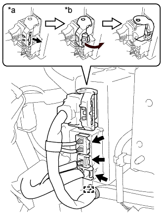 |
Disengage the clamp.
Disconnect the connector from the power steering ECU assembly.
As shown in the illustration, pull out the lock of the lock lever and turn the lock lever to disconnect the connector.
| *a | Pull out the lock |
| *b | Turn the lock lever |
Disconnect the 3 connectors from the power steering ECU.
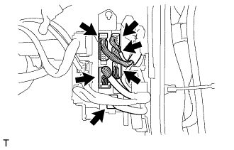 |
Disconnect the 6 front side connectors from the instrument panel junction block assembly indicated as shown in the illustration.
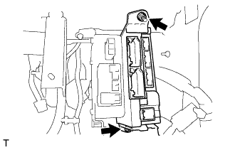 |
Remove the bolt, nut and the instrument panel junction block assembly.
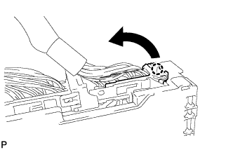 |
Disconnect the connector indicated as shown in the illustration.
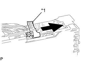 |
Disengage the claw and slide the lever upwards.
| *1 | Lever |
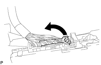 |
Disconnect the connector indicated as shown in the illustration.
Remove the instrument panel junction block assembly.
| 5. REMOVE NETWORK GATEWAY ECU |
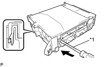 |
Press the claw on the instrument panel junction block assembly side, as shown in the illustration, to release the lock.
With the instrument panel junction block assembly side, insert the screwdriver with its tip wrapped in protective tape between the network gateway ECU and the instrument panel junction block assembly.
| *1 | Protective Tape |
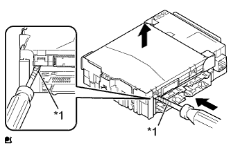 |
Using the screwdriver with its tip wrapped with protective tape, carefully raise the network gateway ECU until the connector becomes disengaged.
| *1 | Protective Tape |
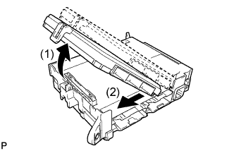 |
Raise the network gateway ECU as shown by arrow 1, and then pull it out as shown by arrow 2 in the illustration.