 |
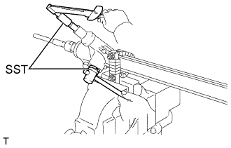
Using SST, tighten the steering rack guide spring cap so that the rotational torque of the pinion shaft reaches the standard value.
- SST
- 09631-10021
09616-00011
- Torque: Preload (turning):
- 0.9 to 1.6 N*m (9.2 to 16.3 kgf*cm, 8.0 to 14.2 in.*lbf)
STEERING GEAR > REASSEMBLY |
| 1. INSTALL STEERING RACK GUIDE |
Apply grease to the steering rack guide spring and the contact surface of the rack guide.
Install the rack guide and the steering rack guide spring.
Apply three bond to 2 or 3 threads of the steering rack guide spring cap.
Temporarily install the steering rack guide spring cap.
| 2. ADJUST TOTAL PRELOAD |
Temporarily install the rack ends sub-assembly RH and LH.
Install the steering rack guide and steering rack guide spring to the steering rack housing.
Apply the three bond to the screw part of steering rack guide spring cap and steering rack housing.
Temporally install the steering rack guide spring cap.
|
Using SST, tighten the steering rack guide spring cap so that the rotational torque of the pinion shaft reaches the standard value.
Apply the three bond to the screw part of lock nut.
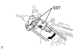 |
Using SST, hold the steering rack guide spring cap and tighten the lock nut.
Set a torque wrench to SST and turn the pinion shaft continuously at a rate of 4 to 6 seconds per turn to inspect the total preload of the steering gear assembly.
| 3. INSTALL STEERING RACK END SUB-ASSEMBLY |
Using SST, install the steering rack end subassembly.
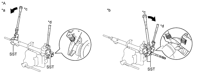
| *A | for LHD | - | - |
| *a | LH Side | *b | RH Side |
| *c | Turn | *d | Hold |
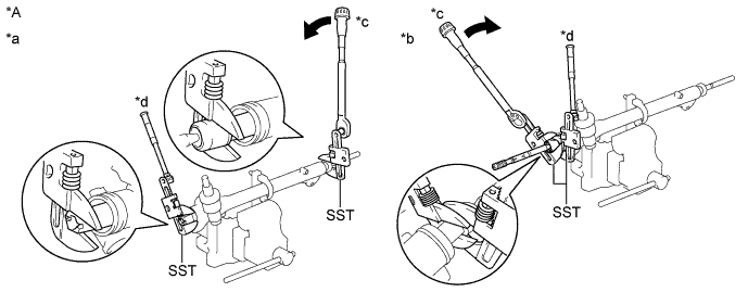
| *A | for RHD | - | - |
| *a | LH Side | *b | RH Side |
| *c | Turn | *d | Hold |
| 4. INSTALL NO. 1 STEERING RACK BOOT |
Wipe the old grease off of the No. 1 steering rack boot and rack end mating groove.
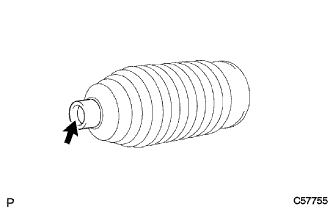 |
Apply silicone grease to the inside of the small opening of a new No. 1 steering rack boot.
Install the No. 1 steering rack boot to the groove on the rack housing.
| 5. INSTALL NO. 1 STEERING RACK BOOT CLAMP |
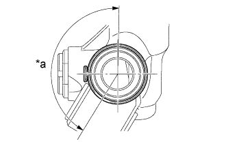 |
Install the new No. 1 steering rack boot clamp to the No. 1 steering rack boot in such a way that the staked part of the clamp is positioned with in the range, as shown in the illustration.
| *a | 150° |
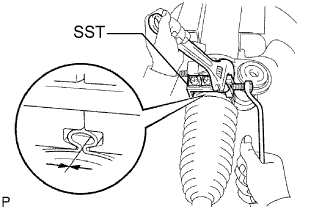 |
Using SST, tighten a new No. 1 steering rack boot clamp as shown in the illustration.
| 6. INSTALL STEERING RACK BOOT CLIP |
Using pliers, install the steering rack boot clip.
| 7. INSPECT RACK AND PINION POWER STEERING GEAR ASSEMBLY |
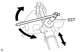 |
Using SST, rotate the pinion shaft to see if both the left and the right steering rack boots expand and contract smoothly.
| 8. INSTALL TIE ROD END SUB-ASSEMBLY LH |
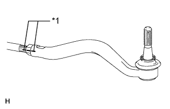 |
Temporarily tighten the lock nut and tie rod end sub-assembly LH to the steering rack end sub-assembly until the matchmarks are aligned.
| *1 | Matchmark |
| 9. INSTALL TIE ROD END SUB-ASSEMBLY RH |