TERMINAL AND CONNECTOR REPAIR PROCEDURES
| Illustration |
Part number |
Part name |
Notes and purpose |
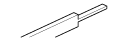 |
09991-00500 |
Lance canceling tool |
For terminal removal⁄
0.64 non-waterproof type, female |
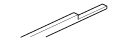 |
09991-00510 |
Lance canceling tool |
For terminal removal⁄
0.64 non-waterproof type, male |
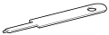 |
09992-01030 |
Lance canceling tool |
For terminal removal⁄
0.64Ⅱ non-waterproof type, male
0.64Ⅱ non-waterproof type, female |
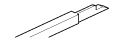 |
09991-00520 |
Lance canceling tool No.1 |
For terminal removal⁄
0.5 non-waterproof type, female
0.5W non-waterproof type, female |
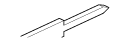 |
09991-00530 |
Lance canceling tool No.2 |
For terminal removal⁄
0.5Ⅱ waterproof type, female
0.64 waterproof type, female
1.0V waterproof type, female |
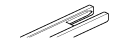 |
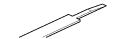
09991-00560 |
Lance canceling tool No.3 |
For terminal removal⁄
0.64 waterproof type, male |
 |
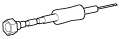
09991-00570 |
Lance canceling tool No.4 |
For terminal removal⁄
1.5 non-waterproof type, male
1.5 non-waterproof type, female |
 |
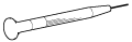
09041-1C570 |
Minus screwdriver 1.8mm |
For terminal removal (to release retainer)⁄
0.64Ⅲ male
Mainly 2.3 - 8.0
etc. |
 |
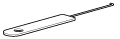
09041-1C580 |
Minus screwdriver 0.9mm |
For terminal removal (to release retainer)⁄
Mainly 1.0 - 2.3II
etc.
|
 |
09991-00550 |
Retainer remover A |
For retainer release⁄
0.64 waterproof type, male |
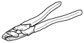 |
09929-00020 |
Clipping tool S (crimping tool) |
For crimp sleeve caulking⁄
Applicable size: SS,S,M |
|
09042-2C100 |
Crimping tool |
For crimp sleeve caulking⁄
Applicable size: S,M, L, LL |
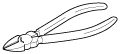 |
- |
Nippers |
For cutting wiring |
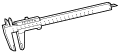 |
- |
Caliper |
For measuring core diameter |
| - |
- |
Dryer
or
heat gun |
For heating heat shrink sleeve⁄
Recommended dryer (100 V AC, 1000 W temperature fuse, 190℃ or higher) |
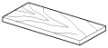 |
- |
Wood plate |
For heat shielding⁄
Size: 300 mm x 100 mm x 10 mm |
These steps must be followed when replacing a terminal.
| [Step 1] Identify the connector and the terminal type |

| [Step 2] Disconnect the terminal from the connector |
| [Step 3] Replace the terminal |
| [Step 4] Push the terminal into the connector |
| [Step 1] Identify the connector and the terminal type |
|
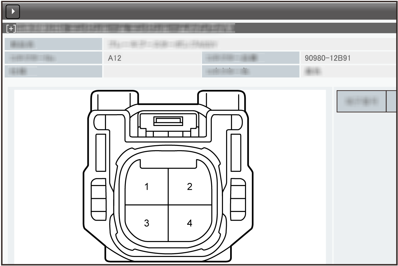
1. Connector body
- Identify the connector part number using the wire diagram connector list.
- Reference:
-
- With regards to the connector supply, it is reference informationan with the item during manual creation.
|
 |
|
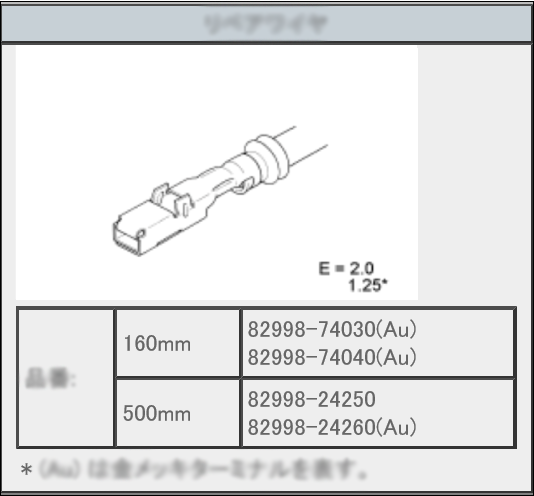
2. Repair wire
- Identify the repair wire part number using the wire diagram connector list.
-
- Reference:
-
- The part number is different depending on whether or not it is gold plated, even for parts of the same shape.
- E=Nominal size
- * displays the nominal size for gold plated terminals.
-
- Notice:
-
- If a gold plated terminal is used, make sure to use another gold plated terminal during replacement.
- Male and female terminals with different materials must not be used.
|
 |
-
- Reference:
-
- Formula for calculating the nominal size of the wire
-
| Nominal size = |
3.14 x (diameter of stripped wire harness)2 |
| 4 |
|
Strand nominal size |
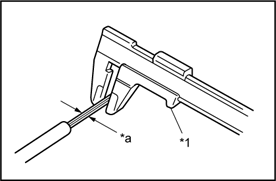 |
| *1 |
Caliper |
| *a |
Wire strand diameter |
|
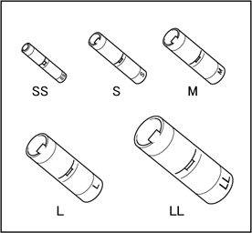
3. Crimp sleeve
- When connecting two wires using a sleeve, select the sleeve according to the following table.
[Wire nominal size and sleeve size]
-
Wire nominal size (mm2) |
Crimp sleeve
size |
| Aluminum wires |
Copper wires |
| 0.5 |
0.13 - 0.5 |
SS |
| 0.75-1.0 |
0.5-1.0 |
S |
| 1.25-2.5 |
1.25-2.0 |
M |
| 3.0 |
3.0 - 5.0 |
L |
| 8.0 |
8.0 |
LL |
|
 |
| [Step 2] Disconnect the terminal from the connector |
1. Disconnect connector
- To pull apart the connectors, pull on the connector itself, not the wire harness.
-
- Reference:
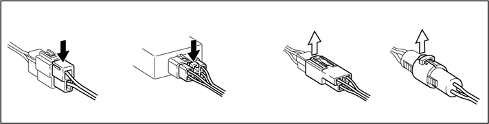
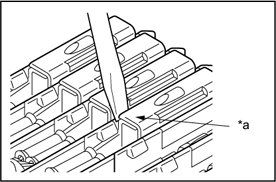
- Confirm the connector type before disconnecting.Mainly a press-down type is used.When attaching or removing a special connector, refer to "How to attach and remove special connectors".
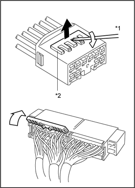
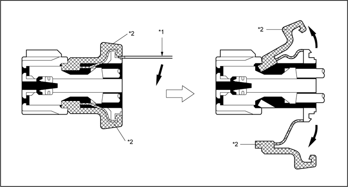
2. Disengage the double locking device or terminal retainer
- The lock must be released before the terminal lance is released and before the terminal is removed from the connector.
- Use the precision screwdriver to release the double locking device or terminal retainer.
-
- Notice:
-
- Do not remove the double locking device or terminal retainer from the connector body.
-
- Reference:
-
- For instructions on how to release each main type, see "How to release the double locking device of each type".
|
 |
 |
Lift up |
| *1 |
Precision screwdriver |
| *2 |
Terminal retainer |
|
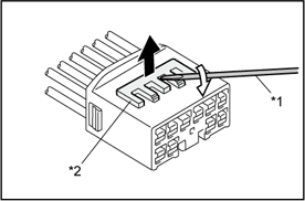
- Type A (for non-waterproof type connector 0.64II, 0.64III, 1.0II, 1.8, 2.3II, 4.8 and 8.0, etc.)
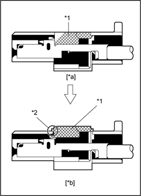
- Using the precision screwdriver, lift the terminal retainer to the temporary lock position.
- Reference:
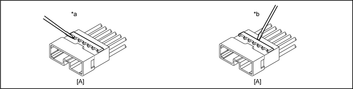
- The precision screwdriver insertion position varies according to the connector shape (number of terminals, etc.), so check the position before inserting it.
|
 |
|
Lift up |
| *1 |
Precision screwdriver |
| *2 |
Terminal retainer |
|
 |
| *1 |
Terminal retainer |
| *2 |
Stopper |
| *a |
Retainer at full lock position |
| *b |
Retainer at temporary lock position |
|
|
 |
|
| *a |
Good example |
A |
Male |
| *b |
Bad example |
|
|
|
3. Disconnect the terminal
Identify the SST part number using the wire diagram connector list.
|
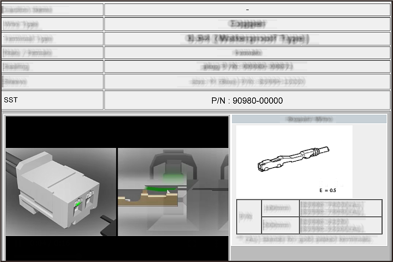 |
- Push the terminal gently into the connector and hold it in this position.
|
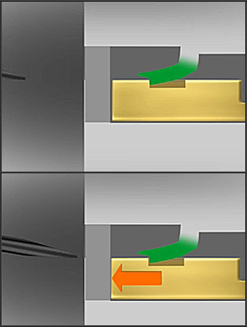 |
- Insert the precision screwdriver into the connector.
- Lift the housing lance in the direction of the arrow using the precision screwdriver, then keep it in place.
-
- Notice:
-
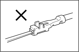
- Do not apply excessive force to the terminal.Do not gouge the terminal with the precision screwdriver.
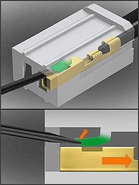
Pull the wire harness and carefully remove the connector from the terminal.
- Notice:
-
- Do not apply excessive force.If the terminal does not come out easily, repeat steps (b) through (e).
|
 |
|
Non-waterproof type |
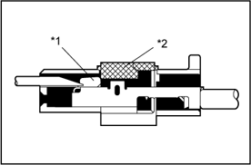 |
| *1 |
Housing lance |
| *2 |
Terminal retainer |
|
-
- Notice:
-
- Do not insert the precision screwdriver in the female terminal box.If you do so, replace the terminal with the new one whether the terminal is broken or not.
|
 |
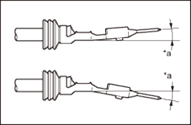
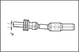
4. Inspect the terminal and the connector for damage
- Inspect the terminal and connector for any deformations or damage.
- Reference:
-
- The terminal and connector are fragile.
- Do not reuse damaged components.
- Check the guideline damage type list to determine whether or not repair is possible.
|
Terminal shape
•Vertical terminal bending |
 |
|
|
•Horizontal terminal bending |
 |
|
|
| [Step 3] Replace the terminal |
1. Select the appropriate repair wire terminal
- Identify the repair wire using the wire diagram connector list.
-
- Reference:
-
- Use the designated repair wire to avoid poor contact due to differing terminal materials such as gold plating.
- E=Nominal size
|
|
2. Replace the wire terminal
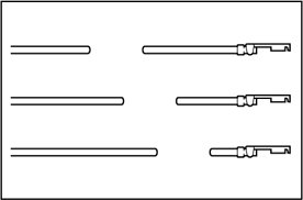
- Use the repair wire as a guide and cut the wire harness to the proper length.
-
- Reference:
-
- When repairing wiring, cut the existing wiring and repair wire with to the same length.
-
- Notice:
-
- Refer to the guidelines for precautions when making repairs.
| Too short: |
Tension on the terminal, splice, or the connector could break the wire. |
| Too long: |
Excess wire near the connector may become pinched or abraded, causing a short circuit. |
|
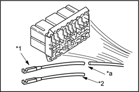 |
| *1 |
Existing terminal |
| *2 |
Repair wire |
| *a |
Cut |
|
-
- Reference:
-
- When connecting a wire harness to multiple spots on the same connector, cut the wire harness as shown on in the illustration.
- Notice:
-
- Refer to the guidelines for precautions when making repairs.
|
 |
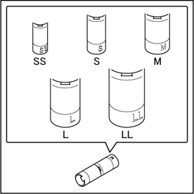
3. Select the correct crimp sleeve from service parts
- Remove about 6 mm of insulation from the tip of the wire harness.
- Measure the diameter of the wire strand using a caliper.
-
- Reference:
-
- Formula for calculating the nominal size of the wire
| Nominal size = |
3.14 x (diameter of stripped wire harness)2 |
| 4 |
|
Strand nominal size |
|
| *1 |
Caliper |
| *a |
Wire strand diameter |
|
- Refer to the table to determine the appropriate size crimp sleeve from the service parts.
-
| Size |
Part number |
Wire nominal size (mm2) |
| Aluminum wires |
Copper wires |
| SS |
82999-50010 |
0.5 |
0.13 - 0.5 |
| S |
82999-52010 |
0.75 - 1.0 |
0.5 - 1.0 |
| M |
82999-52020 |
1.25 - 2.5 |
1.25- 2.0 |
| L |
82999-30020 |
3.0 |
3.0 - 5.0 |
| LL |
82999-60020 |
8.0 |
8.0 |
|
 |
4. Remove the sheath from the existing wire and the repair terminal wire.
- Using the selected sleeve, follow the directions in the table and remove the insulation from the wire harness and repair wire.
-
| |
S - LL |
SS |
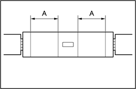
| A (mm) |
8 - 11 |
6 |
|
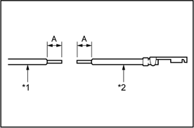 |
| *1 |
Existing harness |
| *2 |
Repair wire |
|
-
- Notice:
-
- Do not damage or cut the wire harness strand.After the sheath is removed, visually check the wire harness. If any damage is found, do the sheath removal again.
|
Good example: |
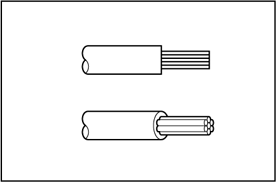 |
Bad example: |
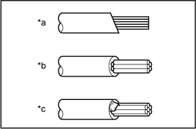 |
| *a |
Wire insulation stripped at an angle |
| *b |
Wire strand cut |
| *c |
Insulation remains on wire |
|
- Follow the directions in the table to identify a heat shrink sleeve that matches the selected sleeve, then place it on the wire harness ahead of time.
-
| Sleeve size |
Heat shrink sleeve part number |
| SS, S, M, L |
82999-30010 |
| LL |
82999-60030 |
|
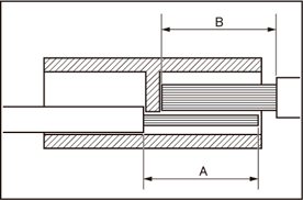
- Insert the wire harness into the sleeve as far as it can go.
|
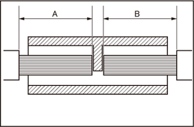 |
* SS sleeve (when the nominal size of the wire harness is 0.13 mm2)
(1)
|
Pass A through the entire sleeve.
|
| (2) |
Insert B into the center of the sleeve as far as it can go. |
* Insert B as far as it can go in the center when both A and B have a harness nominal size of 0.13 mm2.
|
 |
5. Join the strands of the existing wire harness and new terminal wire
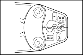
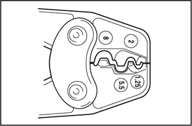
- Follow the instructions in the table to identify a crimping tool and caulking section size that match the selected sleeve.
-
| Sleeve size |
Caulking section size |
Crimp mark |
| SS |
0.5 |
0 |
| S |
1.25 |
1 |
| M |
2 |
2 |
| L |
5.5 |
5 |
| LL |
8 |
8 |
| Part name |
Part number |
| Crimping tool S |
09929-00020 |
| Crimping tool |
09042-2C100 |
|
Crimping tool S
|
Crimping tool
|
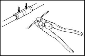
- Squeeze the tool handles to release the ratchet.
- Place the sleeve in the crimping area of the tool and squeeze the handles so that the crimp sleeve is not dropped.
-
- Reference:
-
- Hold area A shown in the illustration.
|
 |
-
- Notice:
-
- Ensure that the convex part on the tool's crimping section comes into contact with the seam of the crimp sleeve.
Squeeze the tool handles until the ratchet is released again.
|
 |
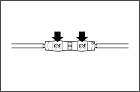
- Check that the crimp mark is correct.
|
 |
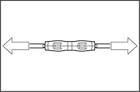
- Pull both ends of the connected wire harness to confirm that the wire harness is not loose.
-
- Notice:
-
- If the wire harness is loose or if caulking was not completed properly due to a combination of the correct crimp sleeve, wire harness, and caulking sections, repeat the process, using a new crimp sleeve.
|
 |
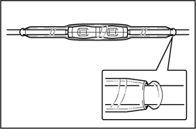
6. Waterproof and insulate the joint area
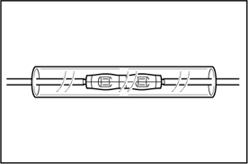
- Place the heat shrink sleeve so that it rests on the center of the junction.
|
 |
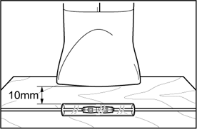
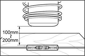
- Using a dryer or heat gun, apply hot air to a heat shrink sleeve for about 10 seconds.
- Reference:
-
- When a dryer is used, keep it about 10 mm away from the shrink sleeve.
- When a heat gun is used, keep it 100 to 200 mm away from the shrink sleeve.
- Notice:
-
- The heat gun emits a high temperature. Watch out for burns.
- Use a wood plate to prevent hot air from being applied to other wires.
|
When a drier is used
 |
When a heat gun is used
 |
- Turn off the dryer or heat gun, and check if a resin substance has come out of the gap between the heat shrink sleeve and wire harness at each sleeve end. Repeat step (b) described above until resin substances come out.
- Notice:
- Note that applying heat for a long period of time may melt the heat shrink sleeve.
|
 |
| [Step 4] Push the terminal into the connector |
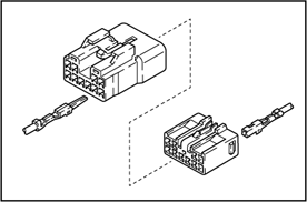
1. Attach the terminal
- Make sure the terminal is positioned correctly.
- Insert the terminal until the housing lance is firmly locked.
|
 |
-
- Reference:
-
- When reusing a terminal, confirm that the terminal lance is in good condition and in the proper position.
- If the terminal lance is not in the proper position on the terminal, use the precision screwdriver to gently bend the terminal back to the original shape.
- Confirm that the other parts of the terminal are in their original shape.
|
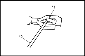 |
| *1 |
Locking clip |
| *2 |
Precision screwdriver |
|
-
- Notice:
-
- Do not readjust or reuse the insulation displacement connector type terminal lance.Always replace the wire with a repair wire.
|
Insulation displacement connector |
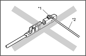 |
| *1 |
Terminal lance |
| *2 |
Precision screwdriver |
|
-
- Notice:
-
- Do not adjust the terminal lance of 0.64 type terminals by bending it, etc.
|
0.64 type |
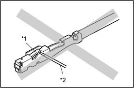 |
| *1 |
Terminal lance |
| *2 |
Precision screwdriver |
|
-
- Notice:
-
- Check the wire condition after repairs.
- A harness that is too long may break due to vibration, resulting in a short circuit.
Tension on the connector side resulting from vibration can deform the connector, causing insufficient pressure and malfunctions.
|
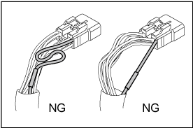 |
Waterproof type connector
- Notice:
-
- Removal of the terminal from the housing will damage the rubber plug material (the wire seal), adversely affecting waterproofing performance. Be sure to replace the housing with a new one.
- Check the withdrawn terminal for the following if when using it again.
- Free of deformation and damage.
- Free of rubber plug material (wire seal), etc.
- Replace any deformed terminals.
2. Attach the terminal retainer or double locking device
Type A (for non-waterproof type connector 0.64II, 1.0I, 1.0II, 1.3, 1.8, 2.3II, 4.8 and 8.0, etc.)
- Set the terminal retainer or double locking device in the full lock position.
- Reference:
- Pull the terminal back gently to check whether it is locked correctly.
- If it cannot be inserted easily, check the terminal and the connector for damage.
- If the housing lance does not lock firmly, the double locking device will not lock, or the terminal retainer will not lock at full lock position, so the terminal will slip out of the connector.
|
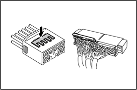
|
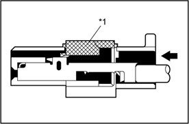 |
|
|
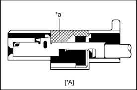 |
| *a |
Full lock position |
| *A |
Female |
|
3. Attachment complete check
- When properly installed, pulling gently on the wire harness will prove the terminal is locked in the connector.
|
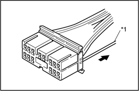 |
|
Pull gently |
| *1 |
Wire |
|
-
- Notice:
-
- For a waterproof type, make sure that a rubber plug or a terminal gasket is securely inserted in the housing.
|
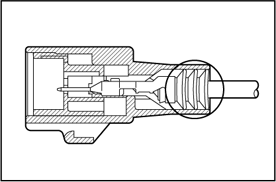 |
4. Restore the repair wire
- Restore the protective material or clamps on the repaired sections of the wire and secure the repair wire to the harness.
-
- Notice:
-
- If it is not possible to restore the protective material or clamp, interference or vibration could cause the harness to break.
|
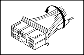 |
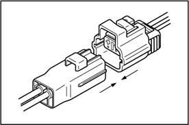
5. Attach the connector
- Fit the male connector to the female connector.
- Notice:
- Do not twist the connector when fitting.
- Insert it until fully locked.
|
 |
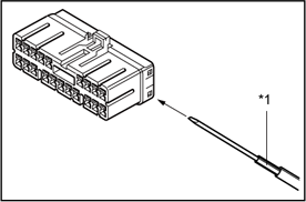
| How to unlock the double locking device of each type |
Type B (for non-waterproof type connector 1.8, 1.0 and TLC, etc.) |
 |
|
|
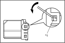
- As shown in the illustration, insert the precision screwdriver in the locking lug access hole at a 45-degree angle, and lift the double locking device as far as it will go.
|
 |
|
|
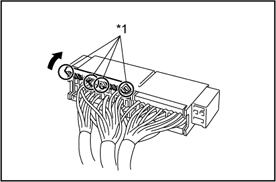
- Remove the precision screwdriver and open the double locking device.
-
- Notice:
-
- The TLC housing is not reusable. Please replace it with a new one after replacement of the terminal.
|
 |
|
|
|
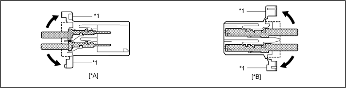 |
|
|
Open |
- |
|
| *A |
Male |
*B |
Female |
| *1 |
Double locking device |
- |
|
|
Type C (for TNS, FTC type connector, etc.)
- Widen the side lock part of the retainer from side to side using the precision screwdriver.
|
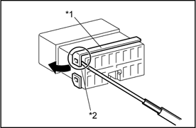 |
|
|
- Inset the precision screwdriver into the gap between the retainer and the terminal itself. Then pry it in the direction of the arrow shown in the illustration and push the retainer up to release the lock.
- Notice:
-
- Do not insert the precision screwdriver too far. Doing so may cause damage on the pressure-contact section of the terminal and the wire harness.
- The TNS housing is not reusable. Please replace it with a new one after replacement of the terminal.
|
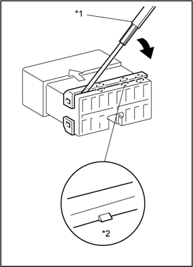 |
| *1 |
Precision screwdriver |
| *2 |
Lock |
|
Type D (for non-waterproof type connector 1.3, etc.)
|
[Case 1]
- Use the precision screwdriver to unlock the double locking device.
|
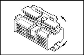 |
|
 |
|
| *1 |
Precision screwdriver |
*2 |
Double locking device |
|
|
[Case 2]
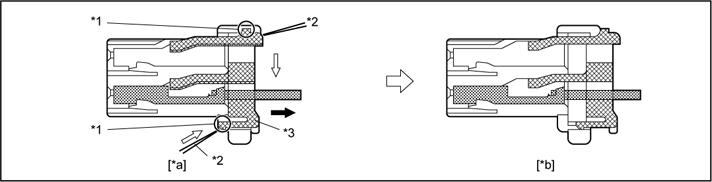
- Using the precision screwdriver, push the terminal retainer locking lug (clip) and lift the terminal retainer to the temporary lock position.
|
 |
|
 |
|
| *1 |
Locking lug |
*2 |
Precision screwdriver |
| *3 |
Terminal retainer |
- |
|
| *a |
Retainer at full lock position |
*b |
Retainer at temporary lock position |
|
|
[Case 3]
- Using the precision screwdriver, lift the retainer to the temporary lock position.
|
 |
| *1 |
Precision screwdriver |
| *2 |
Terminal retainer |
| *3 |
Stopper |
| *a |
Retainer at full lock position |
| *b |
Retainer at temporary lock position |
|
|
[Case 4]
- Insert the precision screwdriver into the service hole and move it in the direction of the arrow to release the lock on side A.
|
 |
|
|
- Use the precision screwdriver to lift the lock on side B and release it, then pull the retainer forward.
|
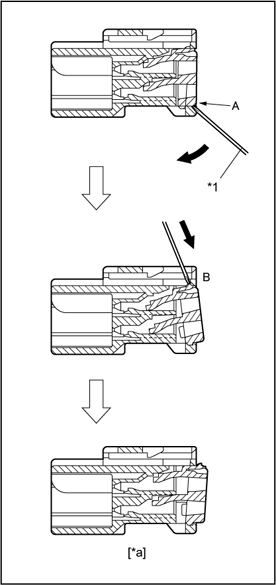 |
| *1 |
Precision screwdriver |
| *a |
Exterior view when double locking device is released |
|
Type E (for waterproof type connector 0.64, 1.8, 2.3, 2.3II, 4.8, 6.3, and 8.0, etc.)
-
- Reference:
-
- The color of the terminal retainer is different than the connector body.
-
- Example:
-
| Terminal retainer |
Connector body |
| Black or white |
Gray |
| Black or white |
Dark gray |
| Gray or white |
Black |
|
[Case 1]
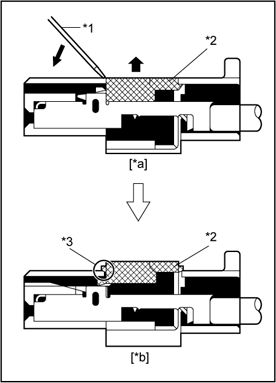
Type that uses retainer remover A.(for male waterproof type connector 0.64)
- Insert the tip of retainer remover A into the service hole to engage it.
- Pull retainer remover A and remove the terminal retainer from the connector.
|
Waterproof connector 0.64 male |
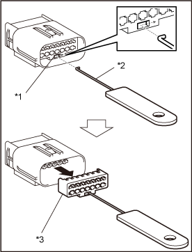 |
| *1 |
Service hole |
| *2 |
Retainer remover A |
| *3 |
Terminal retainer |
|
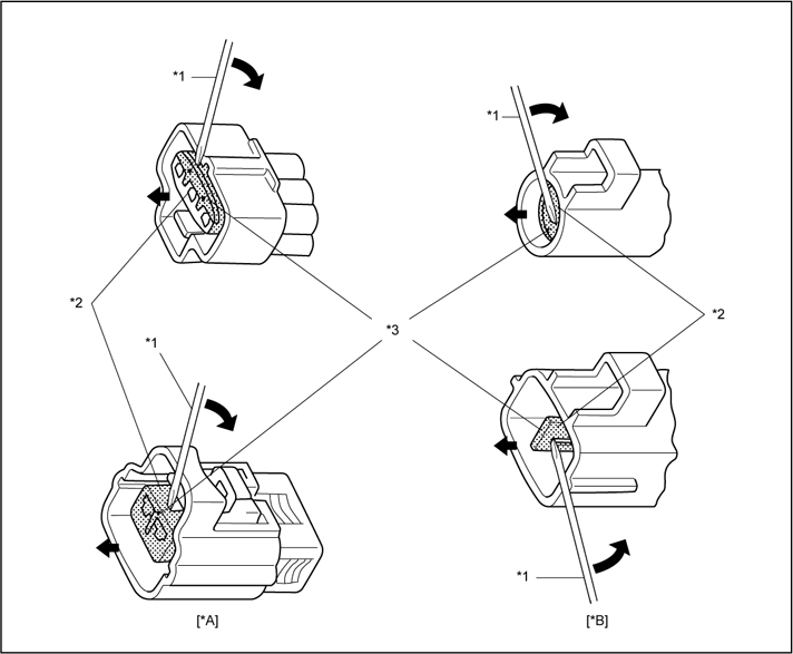
[Case 2]
Type for removing the retainer using a precision screwdriver.(for waterproof type connector 1.8, 2.3, 2.3II, 4.8, 6.3, and 8.0, etc.)
- Insert the precision screwdriver into the terminal retainer access hole (
 mark) and lift the terminal retainer to the temporary lock position.
-
- Reference:
-
- The precision screwdriver insertion position varies according to the connector shape (number of terminals, etc.), so check the position before inserting it.
|
 |
|
| *A |
Female |
*B |
Male |
| *1 |
Precision screwdriver |
*2 |
Terminal retainer |
| *3 |
Access hole( mark) |
- |
|
|
[Case 3]
- Type where the terminal retainer is lifted to the temporary lock position.(pull type)
|
Example:
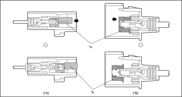 |
|
| *A |
Male |
*B |
Female |
| *a |
Terminal retainer at full lock position |
*b |
Terminal retainer at temporary lock position |
|
-
- Reference:
-
- In some cases, the precision screwdriver must be inserted from the access hole on the side of the housing.
|
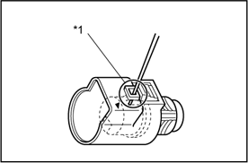 |
|
|
[Case 4]
Type where the terminal retainer is pushed down to the temporary lock position.
- Insert the precision screwdriver straight into the terminal retainer access hole as shown.
Push the terminal retainer down to the temporary lock position.
|
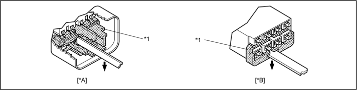 |
|
|
Push down |
- |
|
| *A |
Male |
*B |
Female |
| *1 |
Terminal retainer |
- |
|
|
| |
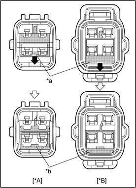 |
| *A |
Male |
| *B |
Female |
| *a |
Retainer at full lock position |
| *b |
Retainer at temporary lock position |
|
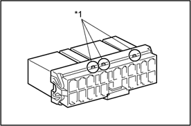
Type F (for C-TYPE connector, etc.)
- Insert the precision screwdriver into the service hole.
|
 |
|
|
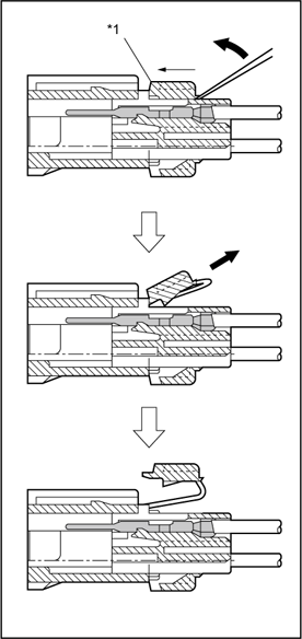
- Move the precision screwdriver in the direction of the thick arrow shown in the illustration and release the lock.
-
- Reference:
-
- Lift the retainer up after moving it to the direction of the thin arrow shown in the illustration.
- Pull the retainer forward by hand and remove the retainer from the housing.
|
 |
|
|
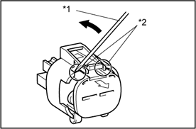
Type G
- Insert the precision screwdriver into location shown in the illustration. Move it in the direction of the black arrow and lift the lock up to release it.
|
 |
| *1 |
Precision screwdriver |
| *2 |
Lock |
|
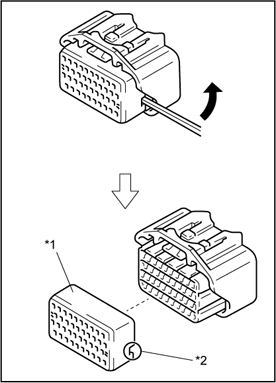
Type H (for 1.0II type connector, etc.)
- Insert the precision screwdriver into the notch of the retainer, then move it in the direction of the arrow using the edge of the housing as the fulcrum. Finally, pull the retainer out.
-
- Notice:
-
- The precision screwdriver must only be inserted into notches. (Inserting it into any other areas may damage the seal ring behind the retainer.)
- Also, pull the retainer straight out by hand after releasing the lock on the opposite side.
|
 |
| *1 |
Retainer (yellow) |
| *2 |
Notch |
|
- Notice:
-
- Do not remove the seal rubber when pulling the terminal out.
- If the seal rubber is comes off when pulling the terminal out, press it down to return it to its original location.
- Never fit the connector if the retainer is not installed.
|
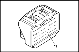 |
|
|
Type I (for S-FPC type connector, etc.)
- Open the cover (white).
|
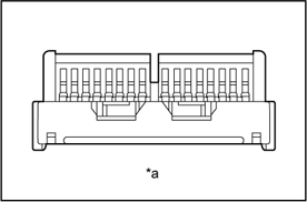 |
|
|
- Remove the side lock of the retainer.(One side)
- Remove the center lock of the housing.
- Remove the side lock of the retainer.(Opposite side)
-
- Notice:
-
- Steps (b) to (d) are in random order.
- The 10-pole housing does not have a center lock.
|
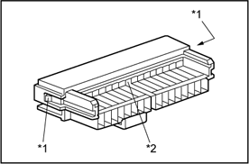 |
| *1 |
Side lock |
| *2 |
Center lock |
|
- Move the retainer to the initial position.(One side)
|
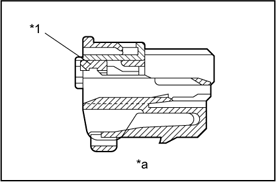 |
| *1 |
Retainer |
| *a |
Initial condition |
|
Type J (for insulation displacement connector, etc.)
- Disassemble the connector
Using the precision screwdriver, release the lock and detach the connector.
-
- Notice:
-
- Do not apply excessive force to the lock arm.
|
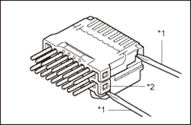 |
| *1 |
Precision screwdriver |
| *2 |
Lock |
|
- With cover: Open the cover connector
Using the precision screwdriver, release the lock and open the cover.
-
- Notice:
-
- Do not apply excessive force to the lock arm.
|
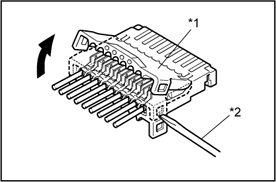 |
| *1 |
Cover |
| *2 |
Precision screwdriver |
|
Type K (for 0.64 type connector, etc.)
- Using the precision screwdriver, lift the retainer to the temporary lock position.
-
- Reference:
-
- The precision screwdriver insertion position varies according to the connector shape (number of cavities, etc.), so check the position before inserting it.
|
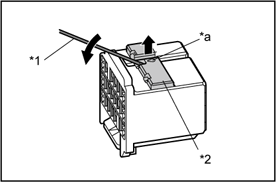 |
|
Lift up |
| *1 |
Precision screwdriver |
| *2 |
Terminal retainer |
| *a |
Precision screwdriver insertion mark |
|
|
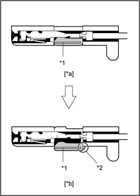 |
| *1 |
Terminal retainer |
| *2 |
Stopper |
| *a |
Retainer at full lock position |
| *b |
Retainer at temporary lock position |
|
|
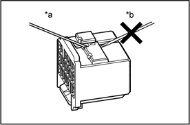 |
| *a |
Good example |
| *b |
Bad example |
|
Type L (for insulation displacement connector (IDC) 0.64, etc.)
- Remove the lower housing.
Using the precision screwdriver, release the lock and remove the lower housing.
- Notice:
-
- Do not apply excessive force to the lock arm.
- Next, mark the upper and lower housing so that you can return them to the original positions.
|
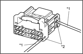 |
| *1 |
Precision screwdriver |
| *2 |
Lock |
|
- Remove the upper housing.
Using the precision screwdriver, release the lock and remove the upper housing from the lock housing.
- Notice:
-
- Do not apply excessive force to the lock arm.
- Next, mark the upper and lower housing so that you can return them to the original positions.
|
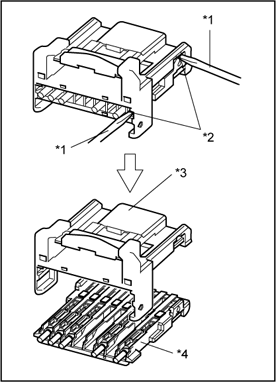 |
| *1 |
Precision screwdriver |
| *2 |
Lock |
| *3 |
Lock housing |
| *4 |
Upper housing |
|
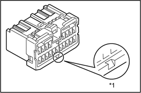
Type M (for 0.64II type connector, etc.)
- Insert the precision screwdriver into the insertion position near the tool mark and lift the terminal retainer to the temporary lock position.
|
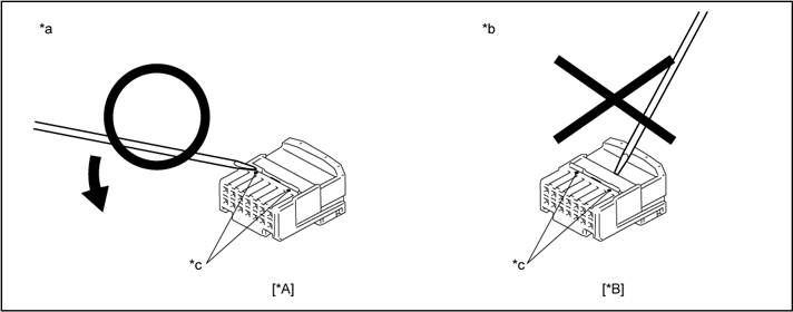 |
|
| *A |
Female |
*B |
Female |
| *a |
Good example |
*b |
Bad example |
| *c |
Tool mark |
- |
|
|
|
Release order
- Notice:
-
- Only insert the precision screwdriver into the tool insertion positions. After releasing the terminal retainer, be sure to check that the terminal retainer has not been deformed.If it has been deformed, replace it with a new one.
- When there are two or more tool insertion positions, release the terminal retainer in the order shown in the illustration.
|
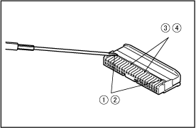 |
Type N (for KITCUT type connector 1.0III, etc.)
- Insert the precision screwdriver into the insertion hole horizontally.
- Push the precision screwdriver as far as it will go.
|
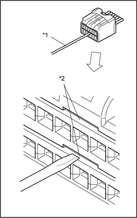 |
| *1 |
Precision screwdriver |
| *2 |
Insertion hole |
|
- Pull out the wire in the direction indicated by the arrow and remove the housing.
|
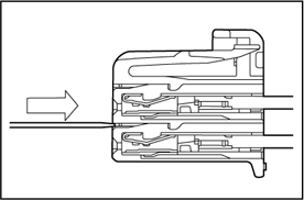 |
| How to disconnect terminals |
Insulation displacement connector type
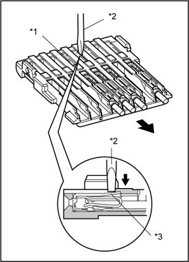
Using the precision screwdriver, push the terminal lance in through the service hole.
Pull the wire harness toward the rear of the connector and carefully remove the terminal from the connector.
- Notice:
-
- Do not apply excessive force.If the terminal does not come out easily, repeat step (a).
- Always change the wire with the repair wire in accordance with [Step 3].
|
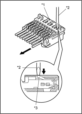 |
| *1 |
Service hole |
| *2 |
Precision screwdriver |
| *3 |
Terminal lance |
|
|
0.64 type |
 |
| *1 |
Service hole |
| *2 |
Precision screwdriver |
| *3 |
Terminal lance |
|
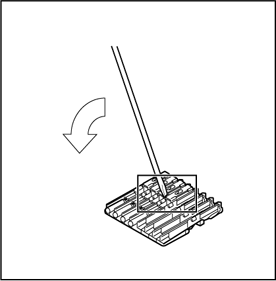
KITCUT type connector 1.0III
Remove the female terminal.
-
| (1) |
Insert the tip of the precision screwdriver at an angle as shown in the illustration. |
| (2) |
Move the precision screwdriver in the direction indicated by the arrow and release the primary lock. |
|
 |
-
| (3) |
Pull the terminal in the direction of the arrow and remove it. |
- Notice:
-
- Do not remove and reinstall the same terminal more than 3 times.
- If the terminal is deformed at all, dispose of it.
- Do not apply excessive force when releasing the primary lock.
- Do not apply excessive force when pulling out the terminal.
- If the terminal does not come out easily, repeat steps (1) to (3).
|
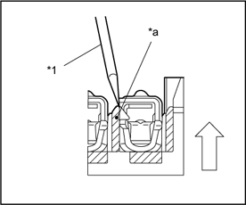 |
| *1 |
Precision screwdriver |
| *a |
Pull out terminal while pushing |
|
Remove the insulation displacement female terminal.
- Notice:
-
- Do not repair the insulation displacement female terminal.
- Always replace the part with a new one if any terminals are removed.
Special-shaped Cavity Type ASET 0.64 Connector
When there are service holes
- Check the position of the service hole and insert the precision screwdriver along the chamfered surface of the housing.
|
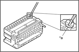 |
| *a |
Precision screwdriver insertion position |
|
Insert the precision screwdriver to below the housing lance.
|
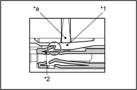 |
| *1 |
Housing lance |
| *2 |
Female Terminal |
| *a |
Insert precision screwdriver |
|
Raise the housing lance and unlatch the female terminal. Be sure not to raise the housing lance above the upper surface of the housing.
|
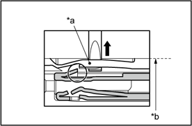 |
| *a |
Lift housing lance |
| *b |
Upper surface of housing |
|
- Carefully remove the female terminal from the housing.
|
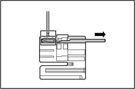 |
|
Pull Out |
|
- Notice:
-
- Do not raise the housing lance above the upper surface of the housing.
- Be extremely careful not to damage the housing or the terminal during the removal of the terminal.
- After removing the housing and terminal, check them for damage and replace them with new ones if any damage is present.
When there are no service holes
Insert the precision screwdriver along the wall surface.
|
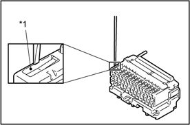 |
|
|
Push the precision screwdriver in below the housing lance.
|
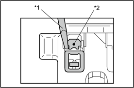 |
| *1 |
Precision screwdriver |
| *2 |
Housing lance |
|
Insert the precision screwdriver underneath the housing lance by pushing it along the thin wall of the housing.
|
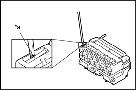 |
| *a |
Insert housing lance below |
|
Raise the housing lance and unlatch the female terminal. Be sure not to raise the housing lance above the upper surface of the housing.
|
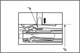 |
| *a |
Lift housing lance |
| *b |
Upper surface of housing |
|
Carefully remove the female terminal from the housing.
- Notice:
-
- Do not raise the housing lance above the upper surface of the housing.
- Be extremely careful not to damage the housing or the terminal during the removal of the terminal.
- After removing the housing and terminal, check them for damage and replace them with new ones if any damage is present.
|
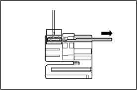 |
|
Pull Out |
|
Rubber plug type
|
[Male]
Remove the rubber plug.
|
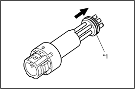 |
|
|
Use the precision screwdriver to push the inner lock down.
Pull the wire in the direction of the arrow while lifting the inner lock to remove the inner section from the outer section.
|
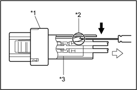 |
| *1 |
Outer section |
| *2 |
Lock |
| *3 |
Inner section |
|
|
[Female]
Remove the rubber plug.
|
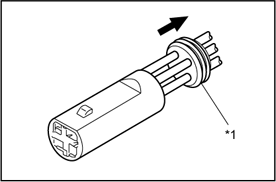 |
|
|
Insert the precision screwdriver into the outer section as shown in the illustration, then push area A of the inner section and remove the inner section from the outer section.
|
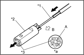 |
| *1 |
Precision screwdriver |
| *2 |
Outer section |
| *3 |
Inner section |
| *a |
Illustration from side B |
|
TLC housing
For non-waterproof type TLC housing, insert the precision screwdriver into the housing from wire harness side.
|
Non-waterproof type TLC housing |
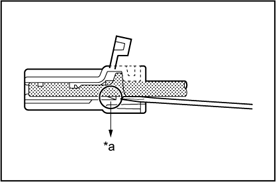 |
| *a |
Insert precision screwdriver from the wire harness side |
|
| How to attach the double locking device of each type |
|
Type B (for waterproof type 0.64, 1.8, 2.3, 2.3II, 4.8, 6.3, and 8.0, etc.)
[Male]
Insert the terminal.
- Reference:
-
- Make sure the terminal is positioned and aligned correctly.
- Insert the terminal with retainer in the temporary lock position.
|
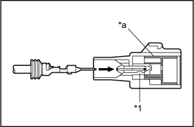 |
| *1 |
Housing lance |
| *a |
Terminal retainer at temporary lock position |
|
- Insert the terminal until the housing lance locks firmly.
- Reference:
-
- Pull the terminal back gently to check whether it is locked correctly.
- If it cannot be inserted easily, check the terminal and the connector for damage or to make sure they are aligned correctly.
|
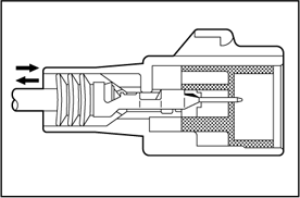 |
-
- Reference:
-
- If the housing lance does not lock firmly, the terminal retainer will also not lock, so the terminal will slip out of the connector.
|
Bad example: |
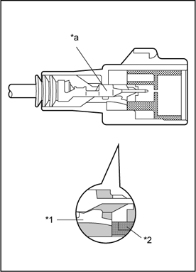 |
| *1 |
Housing lance |
| *2 |
Terminal retainer |
| *a |
Terminal not fully inserted |
|
|
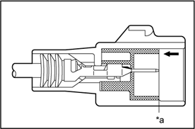
[Case 1]
- Push the terminal retainer in to the full lock position.
|
[Case 1] |
 |
|
|
|
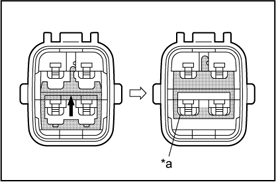
[Case 2]
- Lift the terminal retainer to the full lock position.
| [Case 2] |
 |
|
|
|
[Female]
Insert the terminal.
-
- Reference:
-
- Make sure the terminal is positioned and aligned correctly.
- Insert the terminal with retainer in the temporary lock position.
|
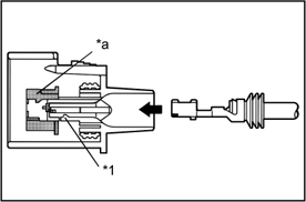 |
| *1 |
Housing lance |
| *a |
Terminal retainer at temporary lock position |
|
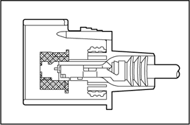
Insert the terminal until the housing lance locks firmly.
-
- Reference:
-
- Pull the terminal back gently to check whether it is locked correctly.
- If it cannot be inserted easily, check the terminal and the connector for damage or to make sure they are aligned correctly.
|
 |
-
- Reference:
-
- If the housing lance does not lock firmly, the terminal retainer cannot lock, so the terminal will slip out of the connector.
|
Bad example: |
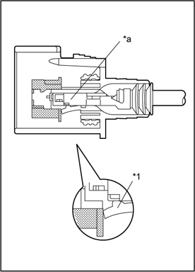 |
| *1 |
Housing lance |
| *a |
Terminal not fully inserted |
|
|
[Case 1]
Push the terminal retainer in to the full lock position.
|
[Case 1] |
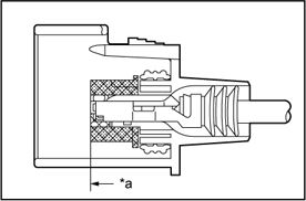 |
|
|
|
[Case 2]
Lift the terminal retainer to the full lock position.
|
[Case 2] |
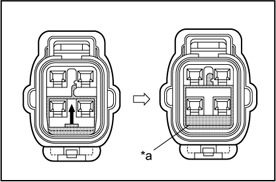 |
|
|
Type C (for 0.64 type connector)
Insert the terminal.
-
- Reference:
-
- Make sure the terminal is positioned and aligned correctly.
|
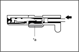 |
| *a |
Temporary lock position |
|
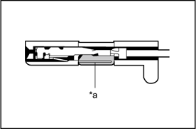
Insert the terminal until the terminal lance locks firmly in place.
- Reference:
-
- Pull the terminal back gently to check whether it is locked correctly.
- If it cannot be inserted easily, check the terminal and the connector for damage or to make sure they are aligned correctly.
- If the terminal lance does not lock firmly, the double locking device or terminal retainer cannot lock in the full lock position, so the terminal will slip out of the connector.
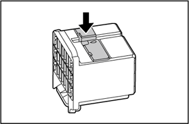
- Set the connector terminal retainer in the full lock position.
|
 |
 |
|
|
Type D (for non-waterproof type 1.3)
|
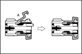
[Case 1]
- First, fit section A.
|
 |
|
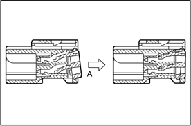
[Case 2]
- Install the A side lock first.
|
 |
- Attach the retainer lock and pull the white cover until you hear a click.
|
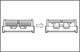 |
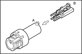
- Attach convex part (A) so that it is correctly aligned with inner lock section B.
|
 |
Insulation displacement connector (non-0.64 type)
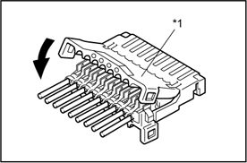
- With cover: Close the cover.
|
 |
|
|
-
- Reference:
-
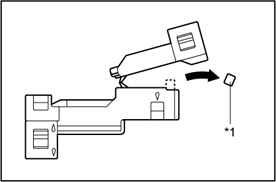
- When replacing with a new connector, cut off the anchor band.
|
 |
|
|
- Attach the connector
- Align the protrusion on the upper housing front lock with the groove in the lower housing front lock and secure it to the rear lock.
- Notice:
- After attaching the housing, securely lock it to make sure that the rear lock arm does not become deformed.
|
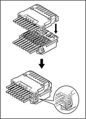 |
Insulation displacement connector (0.64 type)
Push the terminal into the connector until you hear a click.
|
0.64 IDC type |
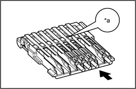 |
|
|
Insulation displacement connector |
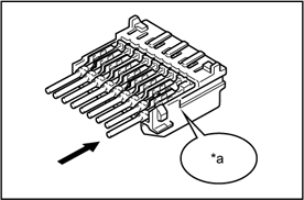 |
|
|
- Install the upper housing on the lock housing.
- Notice:
- Securely lock the housing.
- Be careful not to mistake the upper housing and lower housing when attaching the two pieces.
|
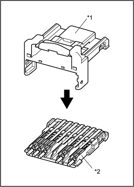 |
| *1 |
Lock housing |
| *a |
Upper housing |
|
- Align the protrusion on the front lock of the upper housing attached to the lock housing with the front lock groove on the lower housing, then secure the rear lock.
- Notice:
- After attaching the housing, securely lock it to make sure that the rear lock arm does not become deformed.
- Make sure that the terminals do not come loose by gently pulling on the wires.
- Be careful not to mistake the upper housing and lower housing when attaching the two pieces.
|
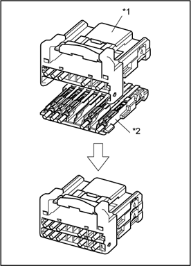 |
| *1 |
Upper housing attached to lock housing |
| *2 |
Lower housing |
|
| How to attach and remove special connectors |
Low fit and lever type connectors
[Case 1]
1. Detach the connector
- Push the location indicated by the arrow.
- The lock is released and the lever pops up.
|
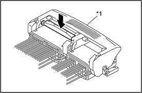 |
|
|
- Lift the lever as far as it will go.
|
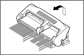 |
- Detach the connector.
-
- Notice:
-
- Do not pull on the wire harness.
|
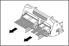 |
2. Attach the connector
- Attach the connector when the lever is in the fully raised position.
-
- Reference:
-
- If the lever is locked in the lowered position, lift the lever as far as it will go within the range of (a) to (c) in Case 1.
|
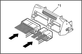 |
|
|
- While holding the connector to ensure that the fitting is not misaligned, press the lever down to lock it until you hear a click.
|
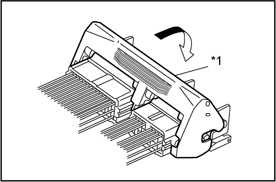 |
|
|
- Confirm that the lever is securely locked.
|
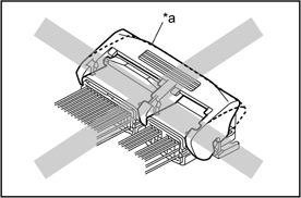 |
|
|
[Case 2]
1. Detach the connector
- Hold area indicated by the arrow.
- The lock is released and the lever pops up.
|
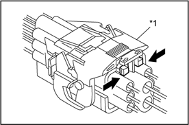 |
|
|
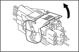
- Lift the lever as far as it will go.
|
 |
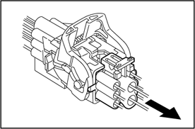
- Detach the connector.
-
- Notice:
-
- Do not pull on the wire harness.
|
 |
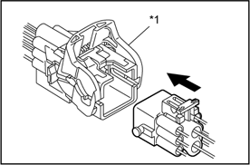
2. Attach the connector
- Attach the connector when the lever is in the fully raised position.
|
 |
|
|
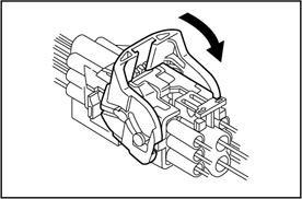
- While holding the connector to ensure that the fitting is not misaligned, press the lever down to lock it until you hear a click.
|
 |
- Confirm that the lever is securely locked.
|
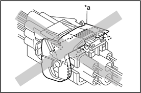 |
|
|
[Case 3]
1. Detach the connector
- Grasp the part indicated in the illustration, using your fingers.
- The lock is released and the lever pops up.
|
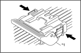 |
|
|
- Lift the lever as far as it will go.
|
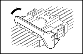 |
- Detach the connector.
-
- Notice:
-
- Do not pull on the wire harness.
|
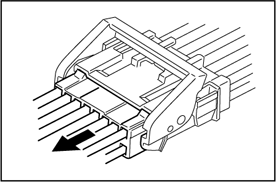 |
2. Attach the connector
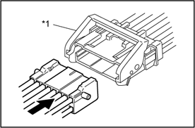
- Attach the connector when the lever is in the fully raised position.
-
- Reference:
-
- If the lever is locked in the lowered position, lift the lever as far as it will go within the range of (a) to (c) in Case 3.
|
 |
|
|
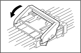
- While holding the connector to ensure that the fitting is not misaligned, press the lever down to lock it until you hear a click.
|
 |
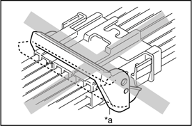
- Confirm that the lever is securely locked.
|
 |
|
|
[Case 4]
1. Detach the connector
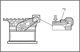
- Push the location indicated by the arrow.
|
 |
|
|
- The lock is released and the lever pops up.
|
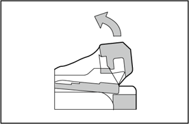 |
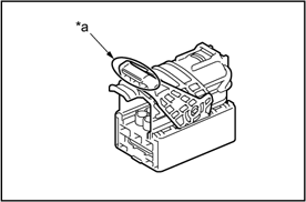
- Rotate the lever to the temporary lock position.
|
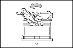 |
| *a |
Rotating lever temporary lock position |
|
- Insert the precision screwdriver into the tool insertion position.
|
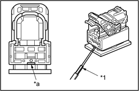 |
| *1 |
Precision screwdriver |
| *a |
Tool insertion position |
|
- Use the precision screwdriver to release the temporary fitting lock.
|
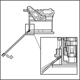 |
- Hold the connector or its cover and pull the connector straight out.
- Notice:
- Make sure that the rotating lever is in the temporary lock position before pulling out the connector.
- Do not forcibly rotate the lever if it does not move, instead confirm that the lever is unlocked.
|
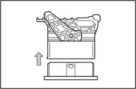 |
2. Attach the connector
- Release the lever lock and then rotate the lever to the temporary lock position.
|
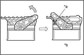 |
| *a |
Stop position |
| *b |
Rotating lever temporary lock position |
|
- Insert the connector until the temporary fitting lock is engaged.
|
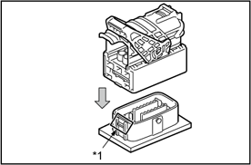 |
| *1 |
Temporary fitting lock |
|
- Reference:
- An audible click can be heard when the temporary fitting lock is engaged.
- When the temporary fitting lock is engaged, the rotating lever will be at 8 to 10° from its temporary lock position.
|
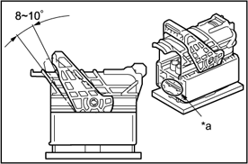 |
| *a |
Temporary fitting lock check |
|
- Notice:
- The lever will not rotate until it is engaged with the mating part.
- Operate the lever control with your finger when rotating the lever via the fitting.
- Do not apply any external force to the rotating lever.
|
 |
|
|
- Rotate the lever to the full lock position.
- Reference:
- An audible click can be heard when the lever is fully locked.
- Notice:
- Do not force the connector to connect by moving it to the right and left.
- Do not apply any external force to the lever other than in the direction of rotation.
- Confirm that the lever is in the full lock position after the connector is connected.
- If you notice anything strange when operating the lever, do not force it to fit. Instead, return it to its initial position and try again.
|
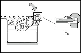 |
| *a |
Rotating lever full lock position |
|
Connector with double locking mechanism
1. Area of use
- Wire harness for SRS airbag deployment
|
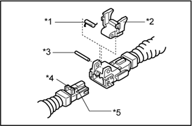 |
| *1 |
Coil spring |
| *2 |
Double locking device pin |
| *3 |
Pin |
| *4 |
Convex part |
| *5 |
Primary locking device |
|
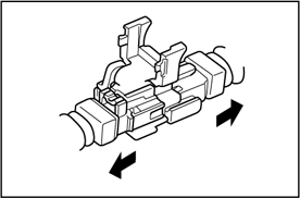
2. Detach the connector
- Release the secondary lock.
|
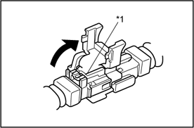 |
|
|
- Release the primary lock and detach the connector.
-
- Notice:
-
- Do not pull on the wire harness.
|
 |
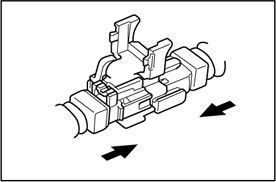
3. Attach the connector
- Attach the primary lock and then attach the connector.
|
 |
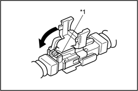
- Attach the secondary lock.
-
- Notice:
-
- The secondary lock cannot be attached until the primary lock is attached.
|
 |
|
|
Bolt-lock connector
1. Area of use
- Engine control computer harness
2. Detach the connector
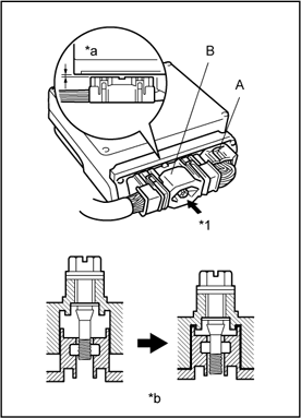
- Remove connector A.
- Using a screwdriver, etc., loosen the bolt until connector B can be removed by hand, then detach the connector.
-
- Reference:
-
- If the bolt cannot be removed, turn it by hand while pulling it forward.
|
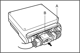 |
| A |
Connector A |
| B |
Connector B |
|
3. Attach the connector
- Temporarily fit connector B.
- Using a screwdriver, etc., tighten the bolt and fit connector B completely.
-
- Notice:
-
- Tighten the bolt until it feels lighter.When doing so, confirm that there is a gap of less than 1 mm from connector B.
- The bolt will continue to turn freely even after it is fitted.
- When using an impact wrench, do not turn it for more than three seconds.(Doing so could generate heat, deforming the housing.)
- Do not attach connector B at an angle.
- Attach connector A.
|
 |
| A |
Connector A |
| B |
Connector B |
| *1 |
Bolt |
| *a |
less than 1mm |
| *b |
Bolt cross section |
|
Locking arm type connector
1. Detach the connector
- Push down on the locking arm to release the lock.Holding the ribs on the rear of the connector, remove the connector.
- Detach the connector.
-
- Notice:
-
- Do not pull on the wire harness.
|
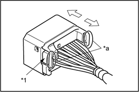 |
| *1 |
Locking arm |
| *a |
Hold the rib to pull the connector |
|
2. Attach the connector
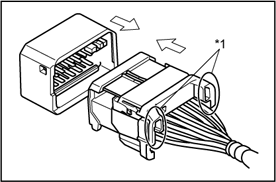
- Align the direction of the lock mechanisms and while holding rear ribs straight, fit the connector in place.
- Insert the connector until it is fully locked, then lightly pull on it to confirm that it is securely locked.
|
 |
|
|
Panel lock type connector
1. Area of use
- [Representative example]
- Floor wire harness
- Door wire harness
|
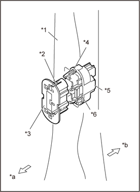 |
| *1 |
Side member outer panel |
| *2 |
Female connector side lock |
| *3 |
Female connector |
| *4 |
Male connector side lock |
| *5 |
Male connector |
| *6 |
Male center lock |
| *a |
Vehicle exterior |
| *b |
Vehicle interior |
|
2. Detach the connector
|
[Side member outer panel lock type connector]
- Remove the grommet from the female connector.
|
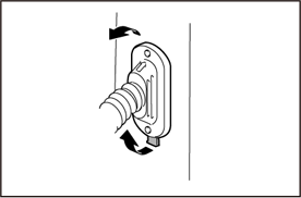 |
- Release the female connector side lock on the upper side while gently pulling on the center section of the female connector.
-
- Reference:
-
- Gently pull the center of the female connector and release the female connector side lock.
- Use a thin-slotted screwdriver to push downward.
-
- Notice:
-
- Make sure to use a thin-slotted screwdriver with its tip wrapped in protective tape to release the female connector side lock.
- Using a screwdriver without protective tape could damage the components.
- After releasing the female connector side lock, check the lock section for any deformities.
- Do not apply excessive force to the lock.
|
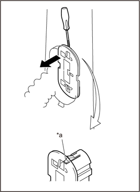 |
| *a |
Tool insertion position |
|
|
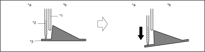 |
|
|
Push the thin slotted screwdriver |
- |
|
| *1 |
Side member outer panel |
*2 |
Thin slotted screwdriver |
| *3 |
Female connector side lock |
- |
|
| *a |
Female side |
*b |
Male side |
|
- Gently pull on the center of the female connector and release the female connector side lock.
-
- Reference:
-
- Gently pull the center of the female connector and release the female connector side lock.
- Use a thin-slotted screwdriver to push upward.
-
- Notice:
-
- Make sure to use a thin-slotted screwdriver with its tip wrapped in protective tape to release the female connector side lock.
- Using a screwdriver without protective tape could damage the components.
- After releasing the female connector side lock, check the lock section for any deformities.
- Do not apply excessive force to the lock.
|
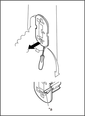 |
| *a |
Tool insertion position |
|
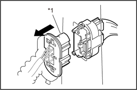
- Pull on the female connector to remove it.
-
- Notice:
-
- Do not pull on the wire harness.
- Make sure that the female connector side locks are released.
|
 |
|
|
3. Attach the connector
|
[Side member outer panel lock type connector]
- Attach the male connector to the side member outer panel.
- Push the male connector center lock so that the center lock protrudes from the side member outer panel.
-
- Reference:
-
- The male connector side lock engages by pushing the male connector.
- Aged and deteriorated male connector side locks may not engage with the panel.If this occurs, raise the tab on the male connector side lock.
-
- Notice:
-
- If the male connector cannot be inserted easily, check the connector for damage.Replace the connector if damaged.
|
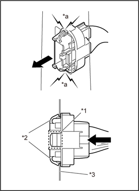 |
| *1 |
Male connector center lock |
| *2 |
Male connector side lock |
| *3 |
Side member outer panel |
| *a |
Click |
|
-
- Notice:
-
- Make sure to attach the male connector to the side member outer panel first.Attaching the female connector to the panel first will result in an unsecured lock.
-
- Reference:
-
- if the male connector center lock does not protrude from the side member outer panel, it will result in an unsecured lock.
- If the side member outer panel is deformed, repair the panel.
|
Bad example: |
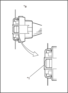 |
| *1 |
Male connector center lock |
| *a |
Male connector center lock not fully inserted |
|
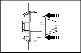
- Continue to push and hold the male connector in position.
-
- Reference:
-
- Continue holding until steps (d) to (e) are complete.
-
- Notice:
-
- if the male connector center lock does not protrude from the side member outer panel, it will result in an unsecured lock.
|
 |
|
Continue pushing |
|
- Push the grommet protrusion and insert the female connector to release the male connector side lock.
-
- Reference:
-
- When the male side locks are released from the side member outer panel, both the male and female connectors will become loose. Continue with the fitting procedure when this happens.
- If aged and deteriorated male connector side locks do not engage with the side member outer panel, press and hold the male connector while keeping the center locks protruding from the panel to fit the side locks.
-
- Notice:
-
- If the female connector is removed while the male connector side locks are released from the panel, the male connector may fall off.
|
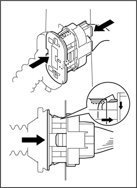 |
-
- Notice:
-
- Push the protrusions on upper and lower portions of the grommet as shown.
-
- Reference:
-
- Pushing the front or rear sides of the grommet can result in an unsecured lock.
|
Grommet protrusion position |
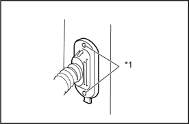 |
|
|
Good example: |
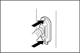 |
Bad example: |
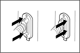 |
- Push the grommet protrusions until the male connector center lock is engaged.
-
- Notice:
- Confirm that the male connector center lock is engaged.
-
- Reference:
-
- Adjust the angle of connectors so that they are perpendicular to the panel. If the male connector side locks are released from the side member outer panel, they tend to be easily tilted.
- Push the connectors toward the center lock, applying force so they are easier to fit.
|
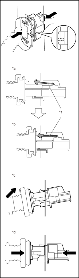 |
| *1 |
Male connector center lock |
| *a |
Before fitting |
| *b |
After fitting |
| *c |
Adjust angle |
| *d |
Push in perpendicular to panel |
|
- After the connectors are fitted, push the side member outer panel until the lower female side lock makes an audible click.
- Confirm that the lower lock is engaged, and then push the upper female connector side lock into the side member outer panel until you hear a click.
-
- Reference:
-
- Engage the lower lock first to make it easier to visually check if the female connector side lock is engaged.
|
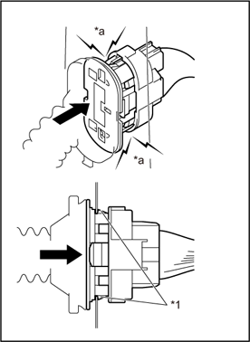 |
| *1 |
Female connector side lock |
| *a |
Click |
|
-
- Reference:
-
- The connectors may become detached if the female connector side locks are not properly engaged.
|
Bad example: |
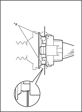 |
| *a |
Female connector side lock not fully inserted |
|
- Attach the grommet.
-
- Notice:
-
- Gently pull the grommet after installation and make sure that there are no gaps between the grommet and the side member outer panel.
- If there are any gaps between the grommet and the side member outer panel, repeat steps (f) through (g).
- If the female connector side lock is not securely engaged with the side member outer panel, waterproofing cannot be guaranteed.
-
- Reference:
-
- If the female connector side locks are not properly engaged with the panel, gaps will be created between the grommet and the panel when the grommet is pulled gently.
|
Good example: |
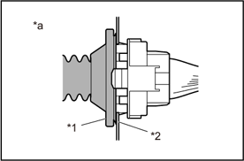 |
| *1 |
Grommet |
| *2 |
Side member outer panel |
| *a |
No gap |
|
Bad example: |
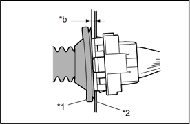 |
| *1 |
Grommet |
| *2 |
Side member outer panel |
| *b |
Gap |
|