BM19Y0E
_01
Vehicle Exterior
_060208
BODY WELD POINT
_0295202
FRONT SIDE MEMBER
F
BODY WELD POINT FRONT SIDE MEMBER ASSEMBLY REPLACEMENT (PATTERN 2)
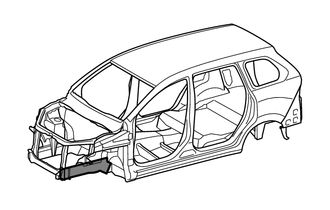
With the front fender apron removed.
REMOVAL
| Symbol Meaning | |
|---|---|

|
Remove Weld Points |

|
Cut with Disc Sander etc. |
REMOVAL POINT
1.
Remove the front part of the front side member sub-assembly.
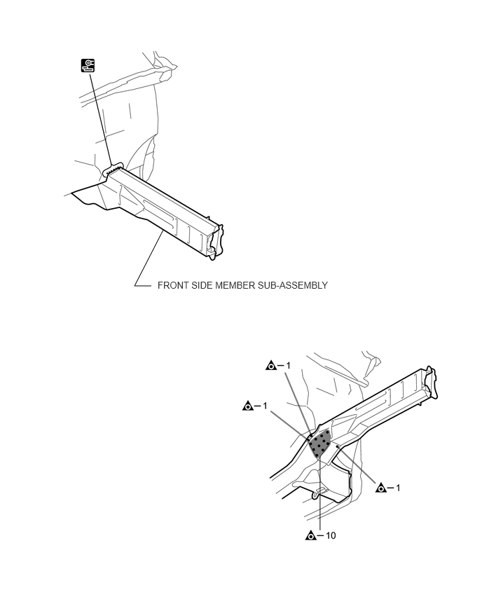
2.25,4.25 2,4.25
2,4.25 2.427,3.417
false
2.344,4.156 5.063,4.719
2.719,0.563
10
false
FRONT SIDE MEMBER SUB-ASSEMBLY
INSTALLATION
| Symbol Meaning | |
|---|---|
|
|
Remove Weld Points |

|
Plug Weld |

|
Fillet Weld |
INSTALLATION POINT
1.
Temporarily install the new parts and measure each part of the new parts in accordance with the body dimension diagram. (See the body dimensions)
2.
Make sure to attach correctly in accordance with the body dimension diagram as this part affects the front wheel alignment.
3.
If the entire supply part is not needed, remove the part of the supply part that is needed.
4.
After welding, apply body sealer and undercoating to the corresponding parts. (See the painting / coating)
5.
After applying the top coat, apply anti-rust agent to the internal panel portion of the closed section structural weld points.
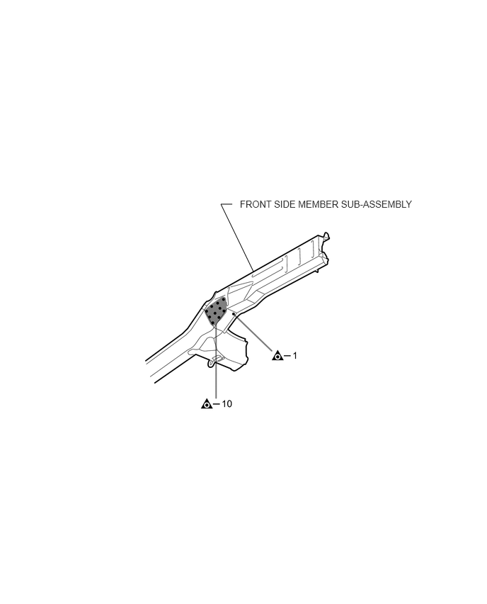
3.729,3.99 3.25,3
3.25,3 3.417,3
false
3.531,2.917 6.198,3.354
2.667,0.438
10
false
FRONT SIDE MEMBER SUB-ASSEMBLY
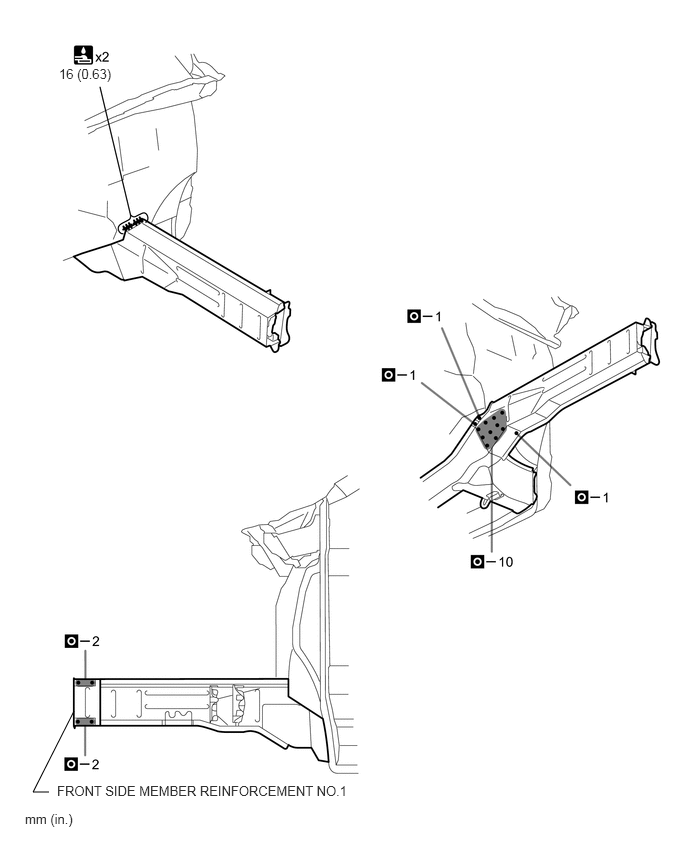
0.51,8.25 0.344,8.25
0.344,8.25 0.771,7.406
false
0.615,0.688 1.99,0.885
1.375,0.198
10
false
16 (0.63)
0.594,8.156 3.719,8.615
3.125,0.458
10
false
FRONT SIDE MEMBER REINFORCEMENT NO.1
0.26,8.448 0.792,8.865
0.531,0.417
10
false
mm (in.)