BODY WELD POINT FIT STANDARD / ADJUSTMENT METHOD ADJUSTMENT
INSPECT HOOD SUB-ASSEMBLY
Check that the clearance measurements are within the standard ranges.
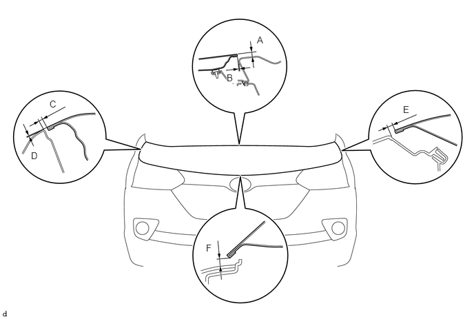
- Standard Clearance (Reference):
Area Measurement Area Measurement A 7.0 mm
(0.276 in.)B 3.0 mm
(0.118 in.)C 2.0 to 5.0 mm
(0.079 to 0.197 in.)D -1.5 to 1.5 mm
(-0.059 to 0.059 in.)E 3.7 to 6.7 mm
(0.146 to 0.264 in.)F 5.5 to 8.5 mm
(0.217 to 0.335 in.)
- HINT:
- ·
Centering bolts are used to mount the hood hinge and the hood lock. The hood and the hood lock cannot be adjusted with the centering bolts in. Substitute standard bolts for the centering bolts when making adjustments.
·Use the same procedure for the RHD and LHD vehicles.
ADJUST HOOD SUB-ASSEMBLY
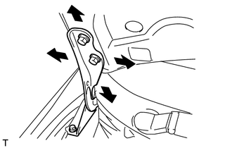
Loosen the 4 hood side hinge bolts.
Move the hood to adjust the clearance to within the standard range.
Tighten the 4 hood side hinge bolts after the adjustment.
- Torque:
- 8.0 N*m (82 kgf*cm, 71 in.*lbf)
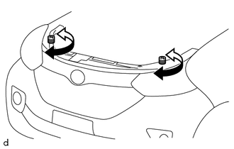
Adjust the height of the hood front end by turning the 2 center hood cushions.
- HINT:
-
The center hood cushion can be raised and lowered by turning it.
Adjust the hood lock assembly.
Remove the front bumper cover.
Remove the upper air inlet grille (except Tropic).
Remove the No. 2 hood lock control cable cover (for Tropic).
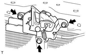
Loosen the 3 bolts.
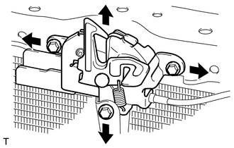
Adjust the hood lock assembly position so that the striker can enter it smoothly.
Tighten the 3 bolts after the adjustment.
- Torque:
- 8.5 N*m (87 kgf*cm, 75 in.*lbf)
Check that the striker can engage smoothly with the hood lock assembly.
INSPECT FRONT DOOR PANEL SUB-ASSEMBLY LH
Check that the clearance measurements are within the standard ranges.
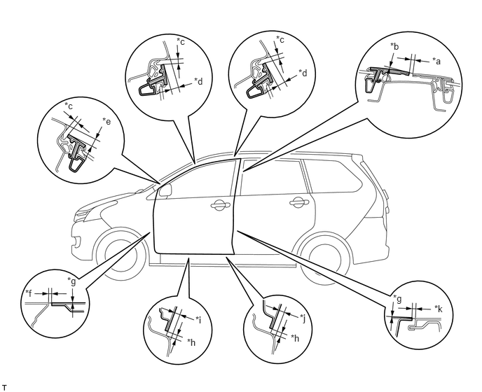
- Standard:
Area Measurement Area Measurement *a 3.6 to 6.6 mm
(0.201 to 0.260 in.)*b -1.6 to 1.4 mm
(-0.063 to 0.055 in.)*c 4.0 to 7.0 mm
(0.158 to 0.276 in.)*d 5.9 to 8.9 mm
(0.232 to 0.350 in.)*e 7.5 to 10.5 mm
(0.295 to 0.413 in.)*f 3.5 to 6.5 mm
(0.138 to 0.256 in.)*g -1.5 to 1.5 mm
(-0.059 to 0.059 in.)*h 4.5 to 7.5 mm
(0.177 to 0.295 in.)*i 5.5 to 8.5 mm
(0.217 to 0.335 in.)*j 4.8 to 7.8 mm
(0.189 to 0.307 in.)*k 3.5 to 6.5 mm
(0.138 to 0.256 in.)- -
- HINT:
- ·
Use the same procedure for the RH and LH sides.
·The procedures described below are for the RH side.
·Centering bolts are used to mount the door hinge onto the vehicle body and door. The door cannot be adjusted with the centering bolts on. Substitute standard bolts (with flange) for the centering bolts when making adjustments.
ADJUST FRONT DOOR PANEL SUB-ASSEMBLY LH
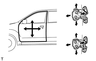
Using SST, adjust the door horizontally and vertically by loosening the body side hinge bolts.
- SST
- 09812-00010
Tighten the body side hinge bolts after the adjustment.
- Torque:
- 24 N*m (245 kgf*cm, 18 ft.*lbf)
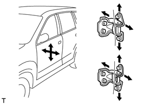
Adjust the door horizontally and vertically by loosening the door side hinge bolts.
Tighten the door side hinge bolts after the adjustment.
- Torque:
- 24 N*m (245 kgf*cm, 18 ft.*lbf)
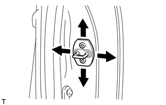
Adjust the striker position by slightly loosening the striker mounting screws and hitting the striker with a plastic-faced hammer.
Tighten the striker mounting screws after the adjustment.
- Torque:
- 13 N*m (131 kgf*cm, 9 ft.*lbf)
INSPECT REAR DOOR PANEL SUB-ASSEMBLY LH
Check that the clearance measurements are within the standard ranges.
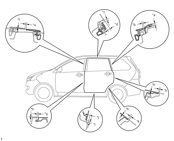
- Standard:
Area Measurement Area Measurement *a 6.2 to 9.2 mm
(0.244 to 0.362 in.)*b 5.1 to 8.1 mm
(0.201 to 0.319 in.)*c 4.0 to 7.0 mm
(0.158 to 0.276 in.)*d 7.1 to 10.1 mm
(0.280 to 0.398 in.)*e 3.6 to 6.6 mm
(0.142 to 0.260 in.)*f -1.6 to 1.4 mm
(0.063 to 0.055 in.)*g 3.5 to 6.5 mm
(0.138 to 0.256 in.)*h -1.5 to 1.5 mm
(0.059 to 0.059 in.)*i 4.5 to 7.5 mm
(0.177 to 0.295 in.)*j 5.0 to 8.0 mm
(0.197 to 0.315 in.)*k 3.0 to 6.0 mm
(0.118 to 0.236 in.)- -
- HINT:
- ·
Use the same procedure for the RH and LH sides.
·The procedures described below are for the RH side.
·Centering bolts are used to mount the door hinge onto the vehicle body and door. The door cannot be adjusted with the centering bolts on. Substitute standard bolts (with flange) for the centering bolts when making adjustments.
ADJUST REAR DOOR PANEL SUB-ASSEMBLY LH
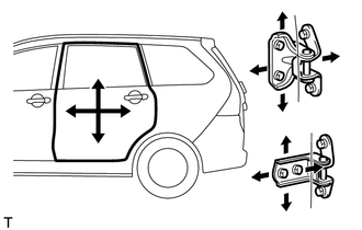
Adjust the door horizontally and vertically by loosening the body side hinge bolts.
Tighten the body side hinge bolts after the adjustment.
- Torque:
- 24 N*m (245 kgf*cm, 18 ft.*lbf)
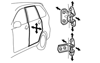
Adjust the door horizontally and vertically by loosening the door side hinge bolts.
Tighten the door side hinge bolts after the adjustment.
- Torque:
- 24 N*m (245 kgf*cm, 18 ft.*lbf)
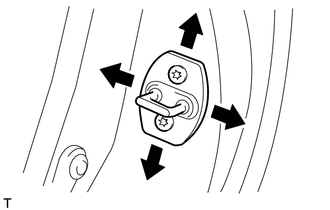
Adjust the striker position by slightly loosening the striker mounting screws and hitting the striker with a plastic-faced hammer.
Tighten the striker mounting screws after the adjustment.
- Torque:
- 13 N*m (131 kgf*cm, 9 ft.*lbf)
INSPECT BACK DOOR PANEL SUB-ASSEMBLY
Check that the clearance measurements are within the standard ranges.
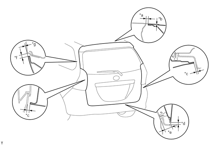
- Standard:
Area Measurement Area Measurement *a 6.0 to 9.0 mm
(0.236 to 0.354 in.)*b -0.5 to 2.5 mm
(-0.020 to 0.098 in.)*c 4.0 to 7.0 mm
(0.158 to 0.276 in.)*d 5.0 to 8.0 mm
(0.197 to 0.315 in.)*e 24.3 to 27.3 mm
(0.957 to 1.075 in.)*f 4.3 to 7.3 mm
(0.169 to 0.287 in.)*g -1.3 to 1.7 mm
(-0.051 to 0.067 in.)- -
- HINT:
-
Centering bolts are used to mount the door hinge onto the vehicle body and door. The door cannot be adjusted with the centering bolts on. Substitute standard bolts (with flange) for the centering bolts when making adjustments.
ADJUST BACK DOOR PANEL SUB-ASSEMBLY
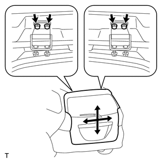
Adjust the door position.
Vertically adjust the door by loosening the door side hinge bolts.
- Torque:
- 18 N*m (184 kgf*cm, 13 ft.*lbf)
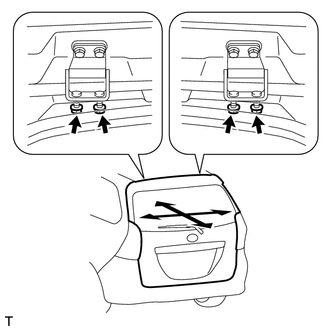
Horizontally adjust the door by loosening the door side hinge nuts.
- Torque:
- 19 N*m (194 kgf*cm, 14 ft.*lbf)
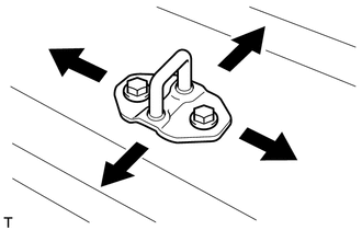
Adjust the striker position.
Adjust the striker position by slightly loosening the striker mounting bolts and hitting the striker with a plastic hammer.
Tighten the striker mounting bolts after the adjustment.
- Torque:
- 6.0 N*m (61 kgf*cm, 53 in.*lbf)