A4Q AUTOMATIC TRANSMISSION / TRANSAXLE AUTOMATIC TRANSMISSION SYSTEM CONTROL AUTOMATIC TRANSMISSION CONTROL
SYSTEM CONTROL
| Control | Function |
|---|---|
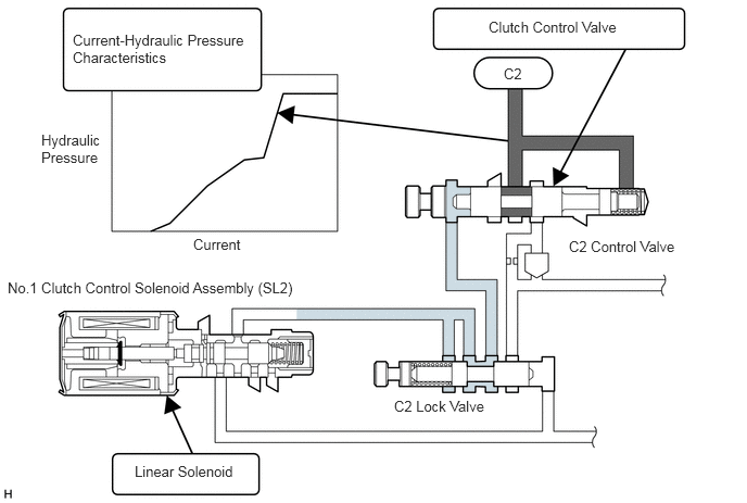
| Direct Hydraulic Pressure Control | This control uses No.1 and No.2 clutch control solenoid assembly to directly control the control hydraulic pressure to the clutches and brakes (C2, C3, B1, B2), without using the shift valve. |
| Clutch to Clutch Pressure Control | The No.1 and No.2 clutch control solenoid assembly minutely controls the clutch pressure in accordance with the engine output and driving conditions. |
| Line Pressure Control | This control uses No.1 clutch control solenoid assembly (SL3) to control the line pressure in 3rd and 4th gears (upon completing shifting) and the reverse gear in accordance with the turbine torque in order to reduce the oil pump load and improve fuel economy. During breaking Drive position ,the DSU is ON (100% duty) and SR is OFF, and the line pressure is reduced. |
| Engine Torque Control | This control retards the engine ignition timing temporarily to improve shift feeling during up or down shifting. |
| Lock-up Timing Control | The TCM sends current to the transmission three-way solenoid assembly (SL, SR) based on signals from each sensor and engages or disengages the lockup clutch. |
| "N" to "D" Squat Control | When the shift lever is moved from N to D, 3, 2, L, the gear is temporarily shifted to 2nd and then to 1st to reduce vehicle squat. |
| Low Gear Inhibitor Control | If a shift-down request is made through the operation of the shift lever while the vehicle is being driven at high speeds, this control maintains the current gear position until the vehicle speed drops below a prescribed speed. |
| Reverse Inhibitor Control | When the driver inadvertently moves the shift lever to the reverse position while the vehicle is running forward at speed above a certain speed, the control works so that the gear can not be put into the reverse position. |
| Low-temperature Shift Restriction Control | Shift restriction is effected if the fluid temperature is low immediately after the vehicle has been started at extremely low temperatures.
·
When the fluid temperature is below -10 °C (14 °F), shifting into 3rd gear is prohibited. ·
When the fluid temperature is below 10 °C (50 °F), shifting into 4th gear is prohibited. |
| Fail-safe | Even if a malfunction is detected in the sensors or solenoids, the TCM effects fail-safe control to prevent the vehicle's drivability from being affected significantly. |
Direct Hydraulic Pressure Control
Unlike the conventional electronically controlled automatic transmission, the A4Q automatic transmission does not contain shift valves. Instead, the shift elements B1, B2, C2 and C3 are directly coupled to the respective control valves. The control valves control the hydraulic pressure of the respective shift control elements in order to shift gears. Furthermore, the No.1 and No.2 solenoid assembly, which generate the signal pressure that acts on the control valves, are connected to the respective control valves.
By regulating the current that is applied to the linear solenoid valves in order to vary their signal pressure, the TCM varies the signal pressure in order to control the output hydraulic pressure.
Clutch to Clutch Pressure Control
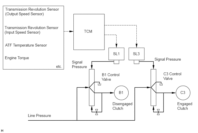
During the transient shift stage, this control simultaneously controls the hydraulic pressure of both the disengaged clutch (brake) and the engaged clutch (brake). This prevents the engine from revving during the transient shift stage or the planetary gear from becoming interlocked, thus realizing a smooth and responsive shifting.
Based on the engine torque information and the transmission fluid temperature provided by the ECM, the TCM effects feedback control on the solenoid valve for the engaged and disengaged clutches (brakes) so that the target rate of change in the input speed is attained. As a result, an efficient torque fluctuation is realized at the output shaft.
FUNCTION
Shift Lock System
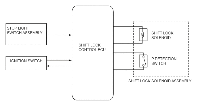
The shift lock mechanism prevents the shift lever from being shifted to any position other than the P, unless the ignition switch is ON, and the brake pedal is depressed. This mechanism helps to prevent unintentional acceleration.
The key interlock device prevents the key from being pulled out after the ignition switch is turned off, unless the shift lever is moved to the P. Thus, the driver is urged to park the vehicle in the P.
The shift lock system mainly consists of the shift lock control ECU, shift lock solenoid, key interlock solenoid and shift lock override button.
The shift lock solenoid assembly has a built-in P detection switch.
FAIL-SAFE
This function minimizes the loss of operation when any abnormality occurs in the input or output signal systems in the TCM.
For details, refer to the corresponding Repair Manual for this model.
DIAGNOSIS
When the TCM detects a malfunction, it makes a diagnosis and memorizes the failed section. Furthermore, the TCM illuminates MIL or blinks the D position indicator light in the combination meter assembly to inform the driver.
The TCM will also store the Diagnostic Trouble Codes (DTCs) of the malfunctions.
The DTCs can be read by connecting an intelligent tester II to the DLC3.
For details, refer to the corresponding Repair Manual for this model.