Home › Steering › POWER ASSIST SYSTEMS › POWER STEERING SYSTEM › 2011.11–2015.08
NM19Y0E _55 Steering _003202 POWER ASSIST SYSTEMS _0016030 POWER STEERING SYSTEM DE DETAILS F

POWER ASSIST SYSTEMS  POWER STEERING SYSTEM  DETAILS  TORQUE SENSOR  


CONSTRUCTION


a.

A type of torque sensor with Hall ICs is used. This makes it possible to shorten the axial length of the sensor, thus increasing the extent of the contraction of the steering column assembly with the energy absorbing mechanism.


b.

The power steering torque sensor is built into the steering column assembly. A multipole magnet is mounted to the input shaft, and a yoke is mounted to the output shaft. The input and output shafts are joined by the torsion bar. A magnetic convergence ring assembly is placed outside of the yoke.
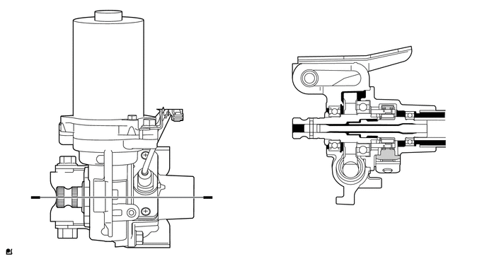
X106595
5.542,2.135 5.958,3 5.958,3 6.135,3 true 5.75,2.188 6.292,2.875 6.292,2.875 6.469,2.875 true 1.458,0.979 0.771,0.458 0.771,0.458 0.594,0.458 true 4.76,1.885 4.188,2.354 4.188,2.354 4,2.354 true 4.74,1.781 4.063,1.26 4.063,1.26 3.885,1.26 true 5.708,1.688 6.24,0.844 6.24,0.844 6.417,0.844 true 5.875,1.771 6.333,1.219 6.333,1.219 6.51,1.219 true 6.167,2.927 6.781,3.542 0.615,0.615 10 *4 0.406,0.375 1.188,1.125 0.781,0.75 10 *1 6.51,2.802 7.094,3.385 0.583,0.583 10 *3 0.469,2.698 1.219,3.281 0.75,0.583 10 A 3.021,2.688 3.823,3.49 0.802,0.802 10 A 3.833,2.26 4.51,2.885 0.677,0.625 10 *2 5.073,3.198 5.771,3.74 0.698,0.542 10 *a 3.74,1.167 4.448,1.792 0.708,0.625 10 *7 6.458,0.76 6.938,1.438 0.479,0.677 10 *6 6.552,1.146 7.031,1.958 0.479,0.813 10 *5
*1 Power Steering Motor *2 Torsion Bar
*3 Magnetic Convergence Ring Assembly *4 Yoke
*5 Input Shaft *6 Multipole Magnet
*7 Output Shaft - -
*a A - A Cross Section - -


c.

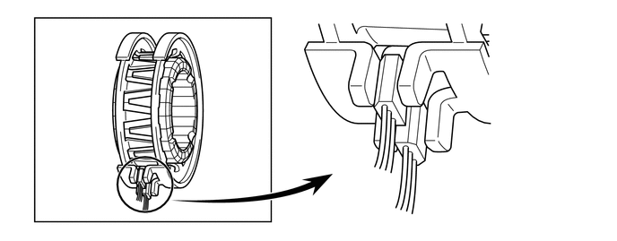
The magnetic convergence ring assembly contains 2 Hall ICs, which face opposite to each other. The system detects the steering direction in accordance with the direction of the magnetic flux that passes between the Hall ICs. Furthermore, the system detects the steering torque in accordance with the amount of change in the magnetic flux density based on the relative displacement of the multipole magnet and the yoke. The power steering ECU assembly monitors the torque sensor signals output by the 2 Hall ICs to detect malfunctions.
X103919
2.135,1.292 2.677,1.292 true 0.927,1.344 1.521,1.344 true 0.875,2.146 1.354,2.146 false 4.823,1.76 5.698,1.76 5.698,1.76 5.708,1.979 true 4.531,1.24 6.479,1.24 6.479,1.24 6.479,1.958 true 0.75,1.26 1.354,1.802 0.604,0.542 10 *2 0.531,0.313 1.177,0.865 0.646,0.552 10 *1 6.396,2 6.969,2.625 0.573,0.625 10 *6 5.646,2.021 6.417,2.698 0.771,0.677 10 *5 2.74,1.208 3.396,1.813 0.656,0.604 10 *4 0.698,2.063 1.281,2.594 0.583,0.531 10 *3
*1 Power Steering Torque Sensor *2 Yoke
*3 Magnetic Convergence Ring Assembly *4 Multipole Magnet
*5 Hall IC 1 *6 Hall IC 2


OPERATION


a.

Straightline Driving

i.

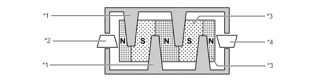
If the vehicle is driven straight and the driver does not turn the steering wheel, the yoke is located in the center between the N and S poles of the multipole magnet. Thus, no magnetic flux passes between the Hall ICs. In this case, the Hall ICs output a specified voltage to the power steering ECU assembly, to indicate that the steering wheel is in the neutral position. Therefore, it does not apply current to the power steering motor.
X100419C02
5.667,1.406 4.635,1.406 4.635,1.406 4.51,1.208 true 4.906,0.896 5.656,0.896 true 5.656,0.344 4.25,0.344 4.25,0.344 4.115,0.51 true 1.063,1.385 3.271,1.385 true 1.125,0.875 2.26,0.875 true 1.094,0.333 2.771,0.333 true 0.906,1.302 1.552,1.781 0.646,0.479 10 *1 0.948,0.781 1.615,1.396 0.667,0.615 10 *2 0.917,0.25 1.5,0.833 0.583,0.583 10 *1 5.698,1.313 6.333,1.781 0.635,0.469 10 *3 5.698,0.813 6.24,1.302 0.542,0.49 10 *4 5.688,0.26 6.24,0.802 0.552,0.542 10 *3
*1 Yoke *2 Hall IC 1
*3 Multipole Magnet *4 Hall IC 2


b.

When Steering

i.

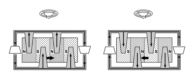
When a driver turns the steering wheel to the right or left, the twist that is created in the torsion bar creates a relative displacement between the multipole magnet and yoke.

·

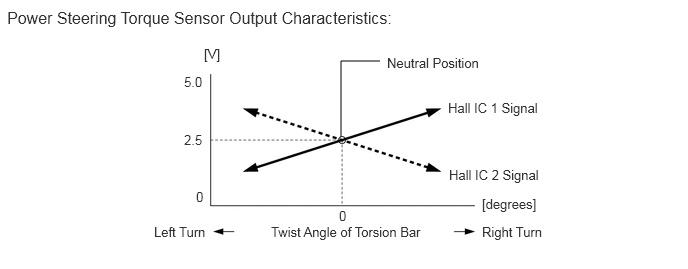
At this time, the magnetic flux from the N to S pole of the multipole magnet passes between the Hall ICs. The system detects the steered direction of the steering wheel in accordance with the direction of the magnetic flux that passes between the Hall ICs. Hall IC 1 and Hall IC 2 are installed facing opposite to each other. As a result, the output characteristics of the 2 Hall ICs are constantly opposite each other. The system monitors the different outputs of these Hall ICs in order to detect malfunctions.

·

The magnetic flux density becomes higher as it gets closer to the center of the respective pole. A Hall IC converts these magnetic flux fluctuations into voltage fluctuations, in order to transmit the turning torque of the steering wheel to the power steering ECU assembly.


ii.

Upon receiving the signals from the power steering torque sensor, the power steering ECU assembly calculates the required assist torque and outputs it to the power steering motor.
X100420
3.167,1.865 3.365,1.948 true 2.479,1.281 2.344,1.281 2.344,1.281 2.26,1.448 true 1.219,2.375 1.479,2.375 true 0.302,2.156 0.448,1.833 true 0.792,1.115 0.969,1.115 false 6.604,1.833 6.833,1.917 true 2.771,2.115 2.927,2.229 true 6.229,2.073 6.385,2.188 true 5.948,1.292 5.792,1.292 5.792,1.292 5.708,1.458 true 4.667,2.375 4.927,2.375 true 3.76,2.188 3.917,1.865 true 4.24,1.115 4.427,1.115 false 4.24,1.323 4.438,1.323 true 0.792,1.323 0.99,1.323 true 5.167,0.75 5.635,1.219 0.469,0.469 10 *b 1.698,0.75 2.302,1.219 0.604,0.469 10 *a 1.042,2.323 1.583,2.792 0.542,0.469 10 *1 0.198,2.208 0.813,2.781 0.615,0.573 10 *2 0.646,1.26 1.281,1.781 0.635,0.521 10 *1 2.875,2.302 3.365,2.729 0.49,0.427 10 *3 3.385,1.875 4.021,2.417 0.635,0.542 10 *4 2.521,1.219 3.104,1.75 0.583,0.531 10 *3 4.49,2.313 5,2.76 0.51,0.448 10 *1 3.667,2.229 4.146,2.698 0.479,0.469 10 *2 4.094,1.26 4.646,1.719 0.552,0.458 10 *1 6.333,2.229 6.854,2.688 0.521,0.458 10 *3 6.854,1.865 7.156,2.448 0.302,0.583 10 *4 6,1.229 6.542,1.698 0.542,0.469 10 *3
*1 Yoke *2 Hall IC 1
*3 Multipole Magnet *4 Hall IC 2
*a Left Turn *b Right Turn


X106966E03
3.552,1.427 3.552,0.635 3.552,0.635 3.958,0.635 false 2.125,0.479 2.885,1.073 0.76,0.594 10 [V] 1.917,0.771 2.698,1.354 0.781,0.583 10 5.0 1.917,1.375 2.667,1.802 0.75,0.427 10 2.5 2.042,1.969 2.688,2.354 0.646,0.385 10 0 3.531,2.167 4.177,2.656 0.646,0.49 10 0 4.031,0.573 5.865,1.146 1.833,0.573 10 Neutral Position 4.667,1.042 6.448,1.74 1.781,0.698 10 Hall IC 1 Signal 4.677,1.74 6.5,2.344 1.823,0.604 10 Hall IC 2 Signal 5.021,2.042 6.354,2.448 1.333,0.406 10 [degrees] 1.604,2.333 3.021,2.792 1.417,0.458 10 Left Turn 5.021,2.333 6.292,2.781 1.271,0.448 10 Right Turn 2.823,2.333 4.885,2.792 2.063,0.458 10 Twist Angle of Torsion Bar 0.073,0.083 4.448,0.625 4.375,0.542 12 Power Steering Torque Sensor Output Characteristics: