PARK ASSIST / MONITORING TOYOTA PARKING ASSIST-SENSOR SYSTEM CONTROL TOYOTA PARKING ASSIST-SENSOR CONTROL
FUNCTION OF MAIN COMPONENTS
The main components in the TOYOTA parking assist-sensor system have the following function:
| Component | Function |
|---|---|
| Ultrasonic Sensor | Detects the distance between the vehicle and the obstacle. |
| Clearance Warning ECU Assembly | ·
Judges the approximate distance between the vehicle and obstacle based on the signals from the ultrasonic sensors. ·
Controlling the actuation of the clearance warning buzzer and indicator light. |
| Clearance Warning Indicator | Displays the approximate distance between the vehicle and the obstacle by flashing the clearance warning indicator. |
| Back-up Light Switch Assembly*1 | Transmits the on/off signals of the back-up light switch assembly to the clearance warning ECU assembly. |
| Park/Neutral Position Switch Assembly*2 | Transmits the R position signal to the clearance warning ECU assembly. |
*1: Models with manual transmission
*2: Models with automatic transmission
SYSTEM CONTROL
The on/off times of the clearance warning buzzer and clearance warning indicator vary as shown in the table below, depending on the distance to the obstacle and the ultrasonic sensor that is detecting the obstacle.
| Detection Area | Detection Distance | Clearance Warning Buzzer and Clearance Warning Indicator ON/OFF Time | |
|---|---|---|---|
| Rear Center | Longest | 1500 +/- 150 mm to 600 +/- 100 mm (59.1 +/- 5.9 in. to 23.6 +/- 3.9 in.) | 150 +/- 15 msec./650 +/- 65 msec. |
| Long | 600 +/- 100 mm to 450 +/- 100 mm (23.6 +/- 3.9 in. to 17.7 +/- 3.9 in.) | 150 +/- 15 msec./150 +/- 15 msec. | |
| Middle | 450 +/- 100 mm to 350 +/- 50 mm (17.7 +/- 3.9 in. to 13.8 +/- 2.0 in.) | 75 +/- 7.5 msec./75 +/- 7.5 msec. | |
| Short | 350 +/- 50 mm or less (13.8 +/- 2.0 in. or less) | Continuous Sound | |
Detection Area
The detection areas of the ultrasonic sensor are as shown in the following illustration.
These detection areas are applicable when positioning a 400 mm (15.7 in.) diameter pole parallel or perpendicular to the ground. The ranges vary depending on the measuring method and type of obstacle.
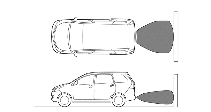

|
Approximately 1500 mm (59.1 in.) | - | - |
Operating Condition
The operating condition of each sensor differs according to its installed position as shown in the table below:
| Installation Position | Operating Condition |
|---|---|
| Rear Center | ·
Ignition switch ON (IG). ·
Shift lever is in R. |