NM19Y0E
_51
Engine / Hybrid System
_041612
2NR-VE ENGINE CONTROL
_0198970
SFI SYSTEM
DE
DETAILS
F
2NR-VE ENGINE CONTROL SFI SYSTEM DETAILS ACCELERATOR PEDAL SENSOR
CONSTRUCTION
a.
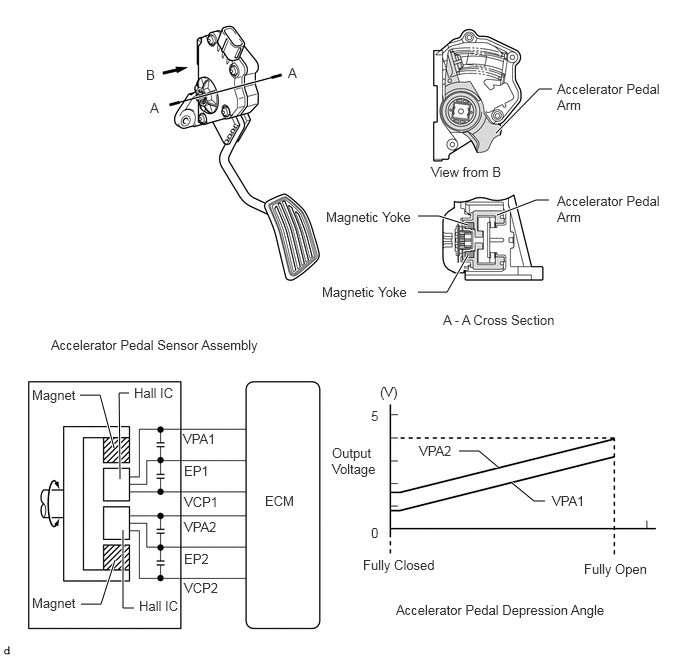
The non-contact type accelerator pedal sensor assembly uses a Hall IC.
b.
The magnetic yoke mounted at the base of the accelerator pedal arm moves around the Hall IC in accordance with the amount of effort applied to the accelerator pedal. The Hall IC converts the changes in the magnetic flux that occur into electrical signals, and outputs them in the form of accelerator pedal effort to the ECM.
c.
This accelerator pedal sensor assembly includes 2 Hall ICs and circuits for the main and sub signals. It converts the accelerator pedal depressed angles into electric signals with two differing characteristics and outputs them to the ECM.
5.167,1.385 5.615,0.927
5.615,0.927 5.75,0.927
true
5.177,2.24 5.583,2.083
5.583,2.083 5.719,2.083
true
4.354,2.25 4.573,2.25
4.573,2.25 4.875,2.344
true
4.354,3.042 4.656,3.042
4.656,3.042 4.875,2.656
true
0.833,4.115 1.042,4.115
1.042,4.115 1.188,4.667
true
0.844,6.292 1.052,6.292
1.052,6.292 1.198,5.833
true
1.25,4.99 1.24,4.094
1.24,4.094 1.344,4.094
true
1.281,5.521 1.281,6.333
1.281,6.333 1.396,6.333
true
4.781,4.698 4.99,4.698
4.99,4.698 5.188,4.865
true
5.333,5.031 5.563,5.219
5.563,5.219 5.677,5.219
true
1.563,1.042 1.719,1.24
0.156,0.198
10
false
A
3,0.677 3.156,0.875
0.156,0.198
10
false
A
5.802,0.844 6.917,1.5
1.115,0.656
10
false
Accelerator Pedal Arm
5.802,2.01 6.927,2.656
1.125,0.646
10
false
Accelerator Pedal Arm
3.396,2.177 4.396,2.688
1,0.51
10
false
Magnetic Yoke
3.354,2.958 4.354,3.469
1,0.51
10
false
Magnetic Yoke
4.615,3.25 5.917,3.667
1.302,0.417
10
false
A - A Cross Section
0.531,3.51 2.917,3.948
2.385,0.438
10
false
Accelerator Pedal Sensor Assembly
0.333,4.031 0.875,4.354
0.542,0.323
10
false
Magnet
0.333,6.198 0.875,6.521
0.542,0.323
10
false
Magnet
1.396,4.01 1.865,4.385
0.469,0.375
10
false
Hall IC
1.448,6.229 1.917,6.604
0.469,0.375
10
false
Hall IC
1.906,4.49 2.521,4.688
0.615,0.198
10
false
VPA1
1.917,4.823 2.531,5.021
0.615,0.198
10
false
EP1
1.917,5.146 2.531,5.344
0.615,0.198
10
false
VCP1
1.917,5.406 2.531,5.604
0.615,0.198
10
false
VPA2
1.917,5.74 2.531,5.938
0.615,0.198
10
false
EP2
1.917,6.042 2.531,6.24
0.615,0.198
10
false
VCP2
2.76,5.135 3.219,5.333
0.458,0.198
10
false
ECM
3.958,4 4.417,4.198
0.458,0.198
10
false
(V)
3.865,4.25 4.021,4.448
0.156,0.198
10
false
5
3.458,4.635 4.01,5.333
0.552,0.698
10
false
Output Voltage
3.865,5.469 4.021,5.667
0.156,0.198
10
false
0
3.781,5.802 4.677,6.198
0.896,0.396
10
false
Fully Closed
6.083,5.844 6.854,6.313
0.771,0.469
10
false
Fully Open
4.125,6.271 6.417,6.75
2.292,0.479
10
false
Accelerator Pedal Depression Angle
1.521,0.698 1.677,0.896
0.156,0.198
10
false
B
4.49,1.708 5.344,2.021
0.854,0.313
10
false
View from B
4.365,4.615 4.979,4.813
0.615,0.198
10
false
VPA2
5.75,5.135 6.365,5.333
0.615,0.198
10
false
VPA1