EXTERIOR PANELS / TRIM BODY STRUCTURE DETAILS SAFETY FEATURES
CONSTRUCTION
Impact Absorbing Structure for Frontal Collision
The cabin has been constructed to limit deformation, with collision energy being dispersed through the upper apron member and the straight front side member, as well as through the use of stronger materials (in the door belt line reinforcement, lockers, floor members and so on).
Bulkheads (cowl top to apron brace and front side rail reinforcement) are used inside the apron upper member and the front side member, thus achieving a structure which effectively transfers the impact energy during a side collision.
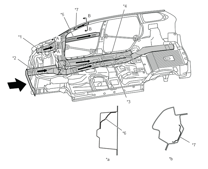
| *1 | Apron Upper Member | *2 | Front Side Member |
| *3 | Floor Member | *4 | Rocker |
| *5 | Door Belt Line Reinforcement | *6 | Cowl Top to Apron Brace |
| *7 | Front Side Rail Reinforcement | - | - |
| *a | A - A Cross Section | *b | B - B Cross Section |

|
Front Impact Energy | - | - |
Impact Absorbing Structure for Side Collision
The cabin has been constructed to limit deformation, with collision energy being dispersed through the rockers and pillars and through the use of stronger materials (in the door belt line reinforcement, floor cross members and so on).
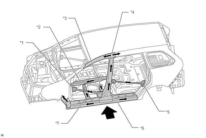
| *1 | Front Door Protection Beam Sub-assembly | *2 | Door Belt Line Reinforcement |
| *3 | Center Floor Panel Reinforcement | *4 | Body Pillar |
| *5 | Rear Door Protection Beam Sub-assembly | *6 | Rocker |
| *7 | Front Floor Cross Member | - | - |
|
|
Side Impact Energy | - | - |
Brake pedal anti-back system
When the brake booster assembly section is pushed backwards during an impact, the clips (bolts) holding the instrument panel reinforcement and brake pedal support sub-assembly in place break away from the brake pedal support sub-assembly. The brake pedal support sub-assembly moves rearward and down along the guide plate. This is intended to move the pedal area of the brake pedal assembly downwards.
- HINT:
-
In an actual accident, it may not function depending on situations.
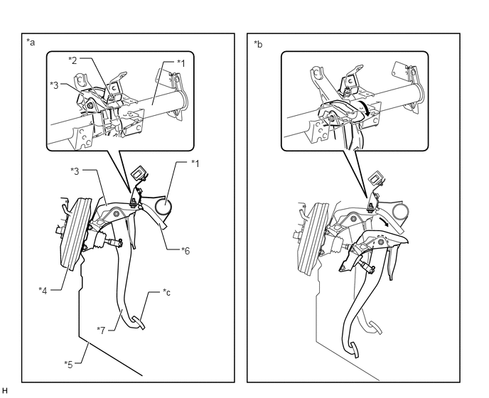
| *1 | Instrument Panel Reinforcement | *2 | Bolt |
| *3 | Brake Pedal Support Sub-assembly | *4 | Brake Booster Assembly |
| *5 | Dash Panel | *6 | Guide Plate |
| *7 | Brake Pedal Assembly | - | - |
| *a | Normal Condition | *b | at Impact |
| *c | Pedal Area of the Brake Pedal Assembly | - | - |
Knee bolster
In the event of a frontal collision, the knee bolsters (No. 1 instrument panel safety pad and No. 2 instrument panel safety pad) wills absorb impact to the driver, reducing injury to the chest and lower extremities.
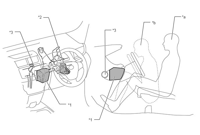
| *1 | No. 1 Instrument Panel Safety Pad | *2 | No. 2 Instrument Panel Safety Pad |
| *3 | Instrument Panel Reinforcement | - | - |
| *a | Normal Condition | *b | at Impact |
Reduction Pedestrian Head Injury
The following shape is used for the cowl and the hood, thus maintaining necessary rigidity and aiming for a reduction of impact against a pedestrian in a collision with a pedestrian.
The space between the cowl top panel outer and cowl top panel inner is ensured. As a result, the impact on pedestrians has been reduced.
A notch structure is adopted for the hood hinge assembly to cushion impact.
The dropout zone for the wiper pivot is ensured to allow the pivot to drop easily, thus reducing the counteracting force on pedestrians. As a result, the impact on pedestrians has been reduced.
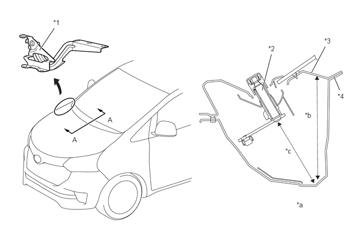
| *1 | Hood Hinge Assembly | *2 | Wiper Pivot |
| *3 | Cowl Top Panel Outer | *4 | Cowl Top Panel Inner |
| *a | A - A Cross Section | *b | Clearance |
| *c | Dropout Zone | - | - |
A longitudinal ribbed structure is adopted for the inner hood to cushion impact.
For the front portion of the hood sub-assembly, a structure with sufficient clearance between the hood panel, hood panel reinforcement and hood lock hook is ensured. As a result, a space is made to absorb the collision impact during an accidental contact with pedestrians, thus reducing the impact on pedestrians.
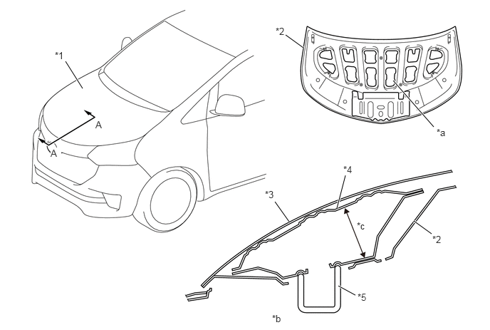
| *1 | Hood Sub-assembly | *2 | Hood Inner Panel |
| *3 | Hood Panel | *4 | Hood Lock Hook Reinforcement |
| *5 | Hood Lock Hook | - | - |
| *a | Longitudinal Ribbed Structure | *b | A - A Cross Section |
| *c | Clearance | - | - |
Reduction Pedestrian Leg Injury
The radiator support apron brace is provided in rear of the radiator support sub-assembly and a front bumper absorber lower is provided in the lower portion of the radiator support sub-assembly, thus achieving a structure made to reduce the impact on pedestrian's legs during a collision.
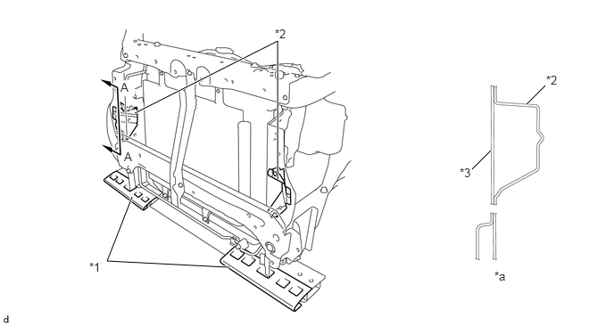
| *1 | Front Bumper Absorber Lower | *2 | Radiator Support Apron Brace |
| *3 | Radiator Support Sub-assembly | - | - |
| *a | A - A Cross Section | - | - |