3SZ-VE ENGINE MECHANICAL CYLINDER HEAD GASKET INSTALLATION
PROCEDURE

 11115
1.INSTALL CYLINDER HEAD GASKET
- NOTICE:
- ·
Remove any oil from the contact surface.
·Be careful of the installation direction.
·Do not damage the cylinder head gasket when installing.
11101
2.INSTALL CYLINDER HEAD SUB-ASSEMBLY
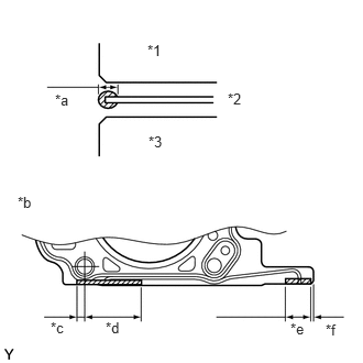
| *1 | Cylinder Head |
| *2 | Cylinder Head Gasket |
| *3 | Cylinder Block |
| *a | 2.5 mm |
| *b | Seal Packing |
| *c | 0 to 4 mm |
| *d | 21 to 27 mm |
| *e | 17 to 23 mm |
| *f | 2 mm |
Apply seal packing as illustrated.
- Seal packing:
Toyota Genuine Seal Packing Black, Three Bond 1207B or equivalent
- NOTICE:
- ·
Remove any oil from the contact surface.
·Install the cylinder head within 3 minutes, and tighten the bolts within 15 minutes of applying the seal packing.
Apply a light coat of engine oil to the threads and seating surfaces of the cylinder head bolts.
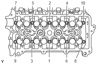
Using several steps, temporarily install the cylinder head bolts with an 8 mm bi-hexagon wrench in the sequence shown in the illustration, then tighten the bolts to the specified torque.
- Torque:
- 34 N*m (347 kgf*cm, 25 ft.*lbf)
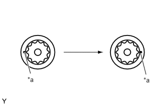
| *a | Paint Mark |
Put paint marks on the front of the cylinder head bolts with paint.
Retighten the bolts by additional 180° in the same sequence as step (c).
Check that all the paint marks are now at the 180° angle to the front.
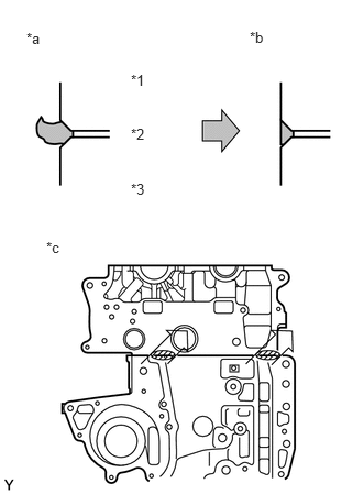
| *1 | Cylinder Head |
| *2 | Cylinder Head Gasket |
| *3 | Cylinder Block |
| *a | Before Wiping |
| *b | After Wiping |
| *c | 0°to 45° to Upper Right |
Wipe off the spilt seal packing.
- NOTICE:
- ·
Wipe off the spilt seal packing on the contact surface between the cylinder block and cylinder head within 15 minutes of applying the seal packing.
·Wipe off the seal packing in the direction of 0°to 45° to the upper right.
13523
3.INSTALL CAMSHAFT TIMING GEAR OR SPROCKET
Clamp No. 2 camshaft in a vise.
Align the knock pin of No. 2 camshaft with the pin groove of the camshaft timing gear or sprocket, then install it with the 3 bolts.
- Torque:
- 8.0 N*m (82 kgf*cm, 71 in.*lbf)
4.INSTALL CAMSHAFT
Apply engine oil to the cam, cylinder head journal, and top of the valve lifter.
Set the camshaft and No. 2 camshaft on the cylinder head with the timing mark of the camshaft timing gear facing upward.
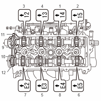
Examine the front marks and numbers on No. 1 camshaft bearing cap and No. 2 camshaft bearing caps and check the sequence order is as shown in the illustration. Then tighten the bolts uniformly in several steps in the sequence shown in the illustration.
- Torque:
- 13 N*m (127 kgf*cm, 9 ft.*lbf)
13520
5.INSTALL CAMSHAFT TIMING SPROCKET ASSEMBLY
Align the knock pin of the camshaft and the pin groove of the sprocket, then install the sprocket onto the camshaft.
While holding the hexagonal lobe of the camshaft, install the camshaft timing sprocket assembly with the bolt.
- Torque:
- 47 N*m (479 kgf*cm, 35 ft.*lbf)
15100
6.INSTALL OIL PUMP ASSEMBLY