3SZ-VE ENGINE MECHANICAL CYLINDER HEAD INSPECTION
PROCEDURE

 1.INSPECT CYLINDER HEAD FOR FLATNESS
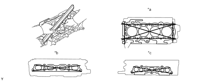
| *a | Cylinder Block Side | *b | Intake Manifold Side |
| *c | Exhaust Manifold Side | - | - |
Using a precision straight edge and feeler gauge, measure the warpage on the cylinder block side and the intake and exhaust manifold sides.
- Maximum warpage:
- Cylinder block side:
0.04 mm (0.0016 in.)
- Intake manifold side:
0.10 mm (0.0039 in.)
- Exhaust manifold side:
0.05 mm (0.0020 in.)
If the warpage is greater than the maximum, replace the cylinder head.
2.INSPECT CYLINDER HEAD FOR CRACKS
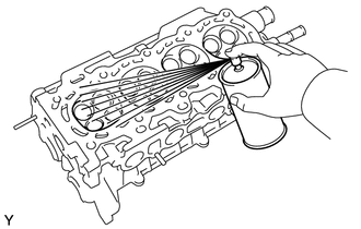
Using a dye penetrate, check the cylinder head for cracks.
13711
3.INSPECT INTAKE VALVE
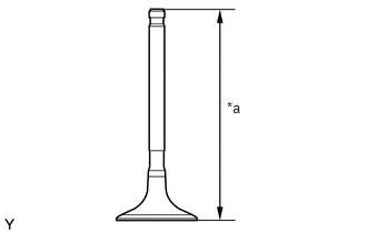
| *a | Overall Length |
Using a vernier caliper, measure the overall length of the intake valve.
- Standard overall length:
88.15 mm (3.4705 in.)
If the overall length is not as specified, replace the intake valve.
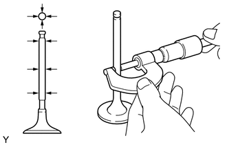
Using a micrometer, measure the diameter of the valve stem.
- Valve stem diameter:
4.975 to 4.990 mm (0.1959 to 0.1956 in.)
If the diameter is not as specified, replace the intake valve.
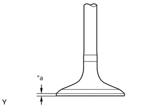
| *a | Margin Thickness |
Using a vernier caliper, measure the thickness of the valve head margin.
- Standard margin thickness:
0.8 mm (0.0315 in.)
If the thickness is not as specified, replace the intake valve.
13715
4.INSPECT EXHAUST VALVE
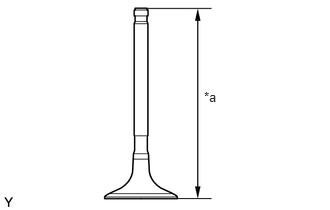
| *a | Overall Length |
Using a vernier caliper, measure the overall length of the exhaust valve.
- Standard overall length:
89.04 mm (3.5055 in.)
If the overall length is not as specified, replace the exhaust valve.
Using a micrometer, measure the diameter of the valve stem.
- Valve stem diameter:
4.965 to 4.980 mm (0.1955 to 0.1961 in.)
If the diameter is not as specified, replace the exhaust valve.
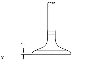
| *a | Margin Thickness |
Using a vernier caliper, measure the thickness of the valve head margin.
- Standard margin thickness:
1.0 mm (0.0394 in.)
If the thickness is not as specified, replace the exhaust valve.
5.INSPECT INNER COMPRESSION SPRING
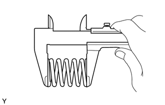
Using a vernier caliper, measure the free length of the compression spring.
- Free length:
54.45 mm (2.1437 in.)
If the free length is not as specified, replace the compression spring.
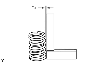
| *a | Deviation |
Using a steel square, measure the deviation of the compression spring.
- Maximum deviation:
1.9 mm (0.0748 in.)
- Maximum angle (reference):
2°
If the deviation is greater than the maximum, replace the compression spring.
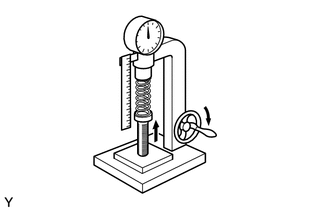
Using a spring tester, measure the tension of the valve spring when it is the specified installed length.
- Installed tension:
140 to 154 N (14.3 to 15.7 kgf, 31.5 to 34.6 lbf) at 37.7 mm (1.4843 in.)
- Maximum working tension:
253 to 279 N (25.8 to 28.4 kgf, 56.9 to 62.7 lbf) at 29.77 mm (1.1720 in.)
If the tension is not as specified, replace the valve spring.
6.INSPECT VALVE GUIDE BUSHING OIL CLEARANCE
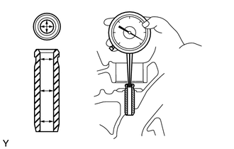
Using a caliper gauge, measure the bore diameter of the valve guide bush.
- Busing inside diameter:
5.010 to 5.022 mm (0.1972 to 0.1977 in.)
If the bore diameter is not as specified, replace the valve guide bush.
7.INSPECT VALVE SEATS
Apply a light coat of prussian blue to the valve face.
Lightly push the valve to the valve seat.
- NOTICE:
-
Do not turn the valve.
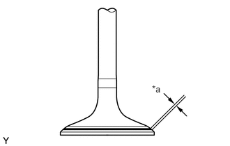
| *a | Width |
Check the valve face and valve seat by performing the following procedures:
If blue appears 360° around the valve face, the valve is concentric. If not, replace the valve.
If blue appears 360° around the valve seat, the guide and valve face are concentric. If not, resurface the valve seat.
Check that the valve seat contact is in the middle of the valve face with the width between 1.2 and 1.6 mm.
13751
8.INSPECT VALVE LIFTER
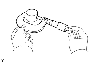
Using a micrometer, measure the lifer diameter.
- Lifter diameter:
27.97 to 27.98 mm (1.1012 to 1.1016 in.)
If the lifter diameter is not as specified, replace the valve lifter.
9.INSPECT VALVE LIFTER OIL CLEARANCE
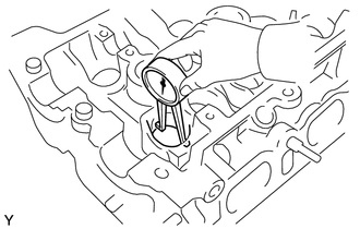
Using a caliper gauge, measure the lifter bore diameter of the cylinder head.
- Lifter bore diameter:
28.00 to 28.02 mm (1.1024 to 1.1032 in.)
If the lifter bore diameter is not as specified, replace the cylinder head.
Subtract the lifter diameter measurement from the lifter bore diameter measurement to calculate the oil clearance.
- Standard oil clearance:
0.025 to 0.055 mm (0.0010 to 0.0021 in.)
If the oil clearance is not as specified, replace the valve lifter or cylinder head.