3SZ-VE ENGINE MECHANICAL CYLINDER BLOCK INSPECTION
PROCEDURE

 1.INSPECT CONNECTING ROD THRUST CLEARANCE
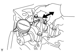
Using a dial indicator, measure the thrust clearance of the connecting rod while moving the connecting rod back and forth.
- Standard thrust clearance:
0.1 to 0.3 mm (0.0039 to 0.0118 in.)
- Maximum thrust clearance:
0.3 mm (0.0118 in.)
If the thrust clearance is greater than the allowable maximum value, replace the connecting rod sub-assembly. If necessary, replace the crankshaft.
2.INSPECT CONNECTING ROD OIL CLEARANCE
Put each cylinder number on the connecting rod and connecting rod cap with paint.
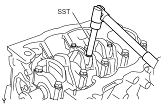
Using SST, remove the bearing cap.
- SST
- 09205-16011
Clean the inside and outside of the bearing, connecting rod end and crank pin.
Check that the bearing and crank pin are not excessively worn or scratched.
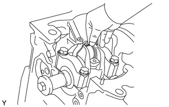
Lay a strip of Plastigage across the crank pin.
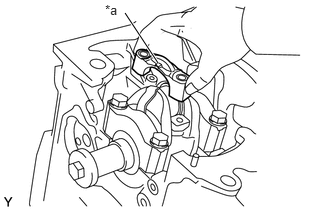
| *a | Front Mark |
Check the combination of the connecting rod and cap, and the front mark of the cap, then install the cap onto the connecting rod.
Apply a light coat of engine oil to the threads and seating surfaces of the bolts.
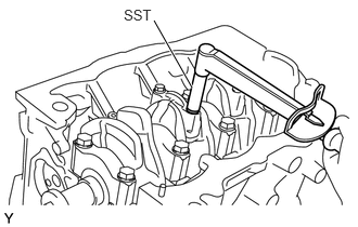
Using SST, temporarily tighten the bolts in several steps, then retighten the bolts to the specified torque.
- SST
- 09205-16011
- Torque:
- 22 N*m (224 kgf*cm, 16 ft.*lbf)
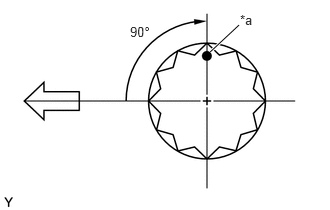
| *a | Paint Mark |

|
Engine Front |
Mark the front of the cap bolts with paint.
Retighten the cap bolts by 90° as shown in the illustration.
- NOTICE:
-
Do not turn the crankshaft when measuring.
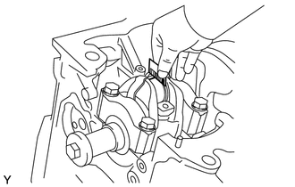
Remove the bearing cap, then measure the Plastigage at its widest point.
- Standard oil clearance:
0.016 to 0.034 mm (0.0006 to 0.0013 in.)
- Maximum oil clearance:
0.07 mm (0.0028 in.)
- NOTICE:
-
Completely remove the Plastigage after the measurement.
-
If the oil clearance is greater than the maximum, measure the crankshaft pin diameter, connecting rod external diameter, and connecting rod bearing thickness. If any of the measurements is not as specified, replace the part.
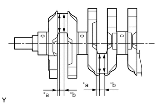
| *a | 4 mm (0.1575 in.) |
| *b | 12 mm (0.4724 in.) |
Measure the crankshaft pin diameter.
- Crankshaft pin diameter:
41.992 to 42.000 mm (1.65323 to 1.65354 in.)
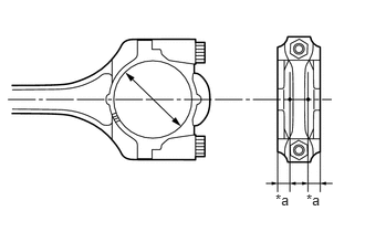
| *a | 4 mm (0.1575 in.) |
Measure the connecting rod external diameter.
- Connecting rod big end bore:
45.000 to 45.008 mm (1.77165 to 1.77197 in.)
Measure the connecting rod bearing thickness.
- Connecting rod bearing center thickness:
1.489 to 1.492 mm (0.0586 to 0.0587 in.)
3.INSPECT CRANKSHAFT THRUST CLEARANCE
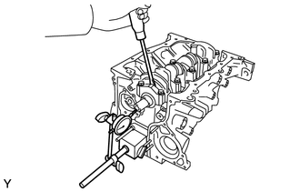
Using a dial indicator, measure the thrust clearance of the crankshaft while moving a screwdriver back and forth.
- Standard thrust clearance:
0.02 to 0.22 mm (0.0008 to 0.0087)
- Maximum thrust clearance:
0.22 mm (0.0087 in.)
If the thrust clearance is greater than the maximum, replace the thrust washer or crankshaft.
- HINT:
-
Thrust washer thickness is 1.94 to 1.99 mm (0.0764 to 0.0784 in.).
4.INSPECT CYLINDER BLOCK FOR FLATNESS
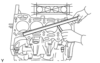
Using a precision straight edge and feeler gauge, measure the warpage on the top surface of the cylinder block at 6 positions.
- Maximum warpage:
0.05 mm (0.0020 in.)
If the warpage is greater than the maximum, replace the cylinder block.
5.INSPECT CYLINDER BORE
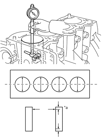
| *a | 45 mm (1.7717 in.) |
Using a cylinder gauge, measure the bore diameter at the 6 positions as illustrated.
- Standard diameter:
72.000 to 72.012 mm (2.8347 to 2.8351 in.)
If the difference is greater than the maximum, replace the cylinder block, or bore the cylinder and use an oversized piston.
Size after boring the cylinder block = (Oversized piston external diameter measurement) + (Oil clearance) - (Honing 0.02 mm).
If the taper and out-of-roundness are greater than the maximum, replace the cylinder block, or bore the cylinder and use an oversized piston.
Size after boring the cylinder block = (Oversized piston external diameter measurement) + (Oil clearance) - (Honing 0.02 mm).
6.INSPECT PISTON SUB-ASSEMBLY WITH PIN
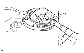
| *a | 12.3 mm (0.4843 in.) |
Using a micrometer, measure the diameter of the piston. Align the micrometer so it is 10 mm from the bottom of the piston and at a right angle (90°) to the piston pin holes.
- Piston diameter:
71.958 to 71.970 mm (2.8330 to 2.8335 in.)
If the diameter is not as specified, replace the piston.
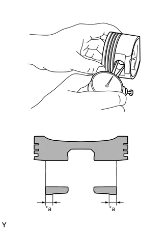
| *a | 8 mm (0.3150 in.) |
Using a caliper gauge, measure the bore diameter all around the piston pin hole at the specified positions. Apply the minimum value as the bore diameter.
- Piston pin hole diameter:
18.007 to 18.010 mm (0.7089 to 0.7091 in.)
If the bore diameter is not as specified, replace the piston.
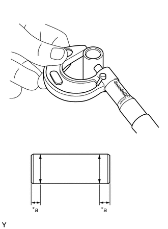
| *a | 8 mm (0.3150 in.) |
Using a micrometer, measure the external diameter all around the piston pin at the specified positions. Apply the maximum value as the external diameter.
- Piston pin diameter:
17.999 to 18.002 mm (0.7086 to 0.7087 in.)
If the external diameter is not as specified, replace the piston.
- NOTICE:
-
Do not change the combinations of the pistons and piston pins so that they can be returned to their original positions when reassembled.
Subtract the piston pin external diameter measurement from the piston pin hole bore diameter measurement to calculate the oil clearance.
- Standard oil clearance:
0.005 to 0.011 mm (0.0002 to 0.0004 in.)
If the oil clearance is not as specified, replace the piston with pin.
7.INSPECT PISTON CLEARANCE
Subtract the maximum external diameter measurement of the piston from the minimum bore diameter measurement of the cylinder thrust to calculate the piston clearance.
- Standard piston clearance:
0.030 to 0.054 mm (0.0012 to 0.0021 in.)
- Maximum piston clearance:
0.054 mm (0.0021 in.)
If the piston clearance is greater than the maximum, replace the piston or cylinder block.
8.INSPECT CONNECTING ROD SUB-ASSEMBLY
Using a rod aligner and feeler gauge, check the connecting rod alignment.
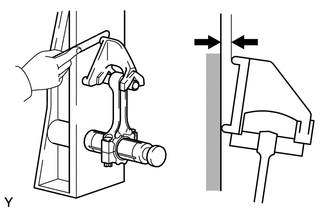
Check for misalignment.
- Maximum misalignment:
0.05 mm (0.0020 in.) per 100 mm (3.94 in.)
If the misalignment is greater than the maximum, replace the connecting rod assembly.
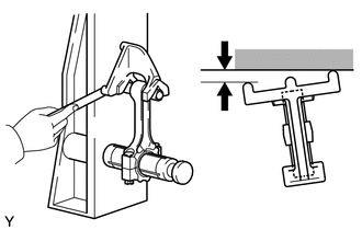
Check for twist.
- Maximum twist:
0.05 mm (0.0020 in.) per 100 mm (3.94 in.)
If the twist is greater than the maximum, replace the connecting rod assembly.
9.INSPECT RING GROOVE CLEARANCE
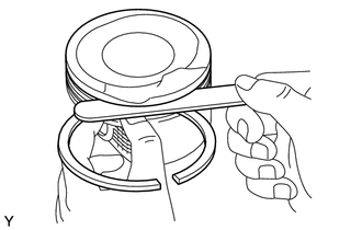
Using a feeler gauge, measure the clearance between the piston ring and ring groove all around the piston.
| Ring | Standard |
|---|---|
| No. 1 | 0.030 to 0.080 mm
(0.0012 to 0.0032 in.) |
| No. 2 | 0.020 to 0.060 mm
(0.0008 to 0.0024 in.) |
If the clearance is not as specified, replace the piston ring.
10.INSPECT PISTON RING END GAP
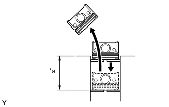
| *a | 45 mm (1.7717 in.) |
Using the piston, push the piston ring until it is 45 mm in from the top of the cylinder block. Using a feeler gauge, measure the end gap.
| Ring | Standard |
|---|---|
| No. 1 | 0.20 to 0.30 mm
(0.0079 to 0.0118 in.) |
| No. 2 | 0.50 to 0.65 mm
(0.0197 to 0.0255 in.) |
| Oil | 0.15 to 0.50 mm
(0.0059 to 0.0197 in.) |
If the end gap is not as specified, replace the piston ring.
11.INSPECT CONNECTING ROD BOLT
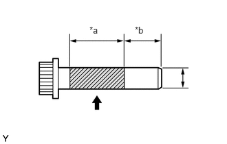
| *a | 19.5 mm (0.7677 in.) |
| *b | 13.5 mm (0.5315 in.) |
Using a vernier caliper, measure the external diameter at the position shown in the illustration.
- Minimum diameter:
7.7 mm (0.3032 in.)
If the external diameter is less than the minimum, replace the connecting rod bolt.
13411
12.INSPECT CRANKSHAFT
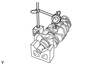
Using a dial indicator and V-blocks, measure the circle runout of the crankshaft.
- Maximum circle runout:
0.03 mm (0.0012 in.)
If the circle runout is greater than the maximum, replace the crankshaft.
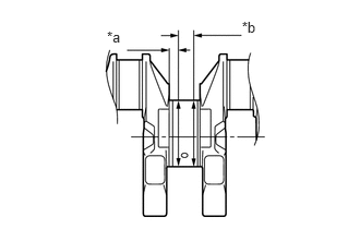
| *a | 5.5 mm (0.2165 in.) |
| *b | 10.4 mm (0.4094 in.) |
Using a micrometer, measure the diameter of the crankshaft journal at the positions shown in the illustration.
- Crankshaft journal diameter:
45.988 to 46.000 mm (1.8106 to 1.8110 in.)
Calculate the taper and out-of-roundness of the journal.
- Maximum taper and out-of-roundness:
0.02 mm (0.0008 in.)
If the taper and out-of-roundness are greater than the maximum, replace the crankshaft.
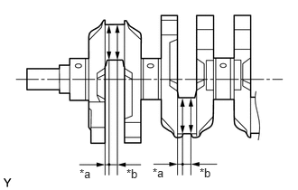
| *a | 4 mm (0.1575 in.) |
| *b | 12 mm (0.4724 in.) |
Using a micrometer, measure the diameter of the crank pin at the positions shown in the illustration.
- Crankshaft pin diameter:
41.992 to 42.000 mm (1.6532 to 1.6535 in.)
Calculate the taper and out-of-roundness of the crank pin.
- Maximum taper and out-of-roundness:
0.02 mm (0.0008 in.)
If the taper and out-of-roundness are greater than the maximum, replace the crankshaft.
13.INSPECT CRANKSHAFT OIL CLEARANCE
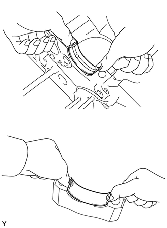
Clean the journal and bearing.
Install the upper bearing with the oil groove onto the cylinder block, the lower bearing onto the bearing cap.
Install the crankshaft into the cylinder block.
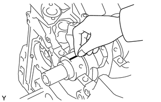
Lay a strip of Plastigage across the crankshaft journal.
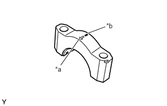
| *a | Front Mark |
| *b | Number |
Check the front mark and imprinted number on the bearing cap, then install the bearing cap onto the cylinder block.
Apply a light coat of engine oil to the threads and seating surfaces of the bolts.
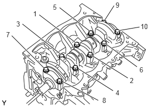
Temporarily tighten the bolts in several steps in the sequence shown in the illustration, then tighten the bolts to the specified torque.
- Torque:
- 59 N*m (602 kgf*cm, 44 ft.*lbf)
- NOTICE:
-
Do not turn the crankshaft when measuring.
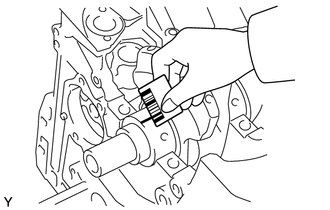
Remove the bearing cap, then measure the Plastigage at its widest point.
- Standard oil clearance:
0.016 to 0.040 mm (0.0006 to 0.0016 in.)
If the width is not as specified, replace the bearing.
- NOTICE:
-
Completely remove the Plastigage after the measurement.
- HINT:
- ·
To select the correct bearing size, calculate the bearing number by adding together the numbers imprinted on the cylinder block and crank journal.
·Example:
Imprinted number on the cylinder block is 1.
Imprinted number on the crank journal is 2.
1 + 2 = 3
Select the bearing with the bearing number 3.
| Number | Cylinder Block Bearing Hole Diameter |
|---|---|
| 1 | 50.000 to 50.006 mm (1.9685 to 1.9687 in.) |
| 2 | 50.007 to 50.012 mm (1.9688 to 1.9690 in.) |
| 3 | 50.013 to 50.018 mm (1.9690 to 1.9692 in.) |
| Number | Crankshaft Journal External Diameter |
|---|---|
| 1 | 45.995 to 46.000 mm (1.8108 to 1.8110 in.) |
| 2 | 45.988 to 45.994 mm (1.8106 to 1.8108 in.) |
| Number | Crankshaft Bearing Thickness |
|---|---|
| 2 | 1.989 to 1.992 mm (0.0783 to 0.0784 in.) |
| 3 | 1.992 to 1.995 mm (0.0784 to 0.0785 in.) |
| 4 | 1.995 to 1.998 mm (0.0785 to 0.0787 in.) |
| 5 | 1.998 to 2.001 mm (0.0787 to 0.0788 in.) |
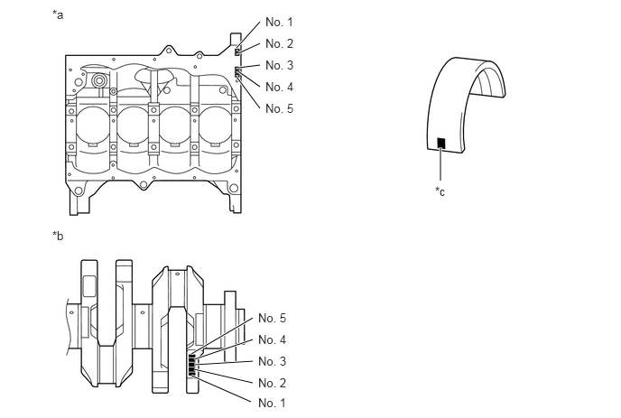
| *a | Cylinder Block Bearing Number | *b | Crankshaft Journal Number |
| *c | Number Mark | - | - |