K3-VE ENGINE MECHANICAL ENGINE UNIT INSPECTION
PROCEDURE

 13506
1.INSPECT CHAIN SUB-ASSEMBLY
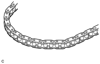
Visually check the timing chain for wear and cracks. If the timing chain is worn or cracked, replace the timing chain and check the sprocket.
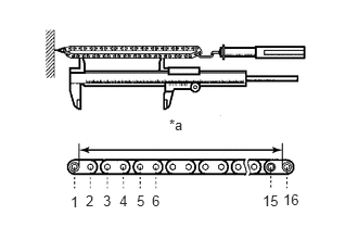
| *a | Measuring Area |
Pull the chain with a force of 225 N (22.9 kgf, 50.6 lbf) as shown in the illustration.
Using a vernier caliper, measure the length of 15 links.
- Maximum chain elongation:
93.121 mm (3.6662 in.)
- HINT:
-
Perform the measurement at 3 random places. Use the average of the measurements.
If the average elongation is greater than the maximum, replace the chain.
13545
2.INSPECT CHAIN TENSIONER PLUNGER
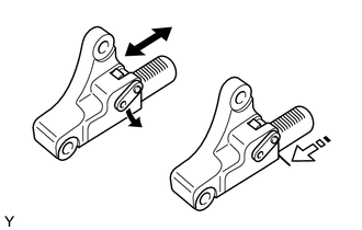
Check that the chain tensioner plunger moves smoothly when the stopper plate of the chain tensioner plunger is pushed by hand.
Release the stopper plate. Check that the chain tensioner plunger does not move with the stopper plate locked, even if the chain tensioner plunger is pushed by hand.
13520
3.INSPECT CAMSHAFT TIMING SPROCKET ASSEMBLY
- NOTICE:
-
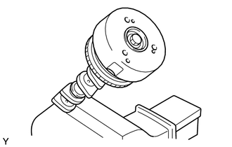
Do not dismantle camshaft timing sprocket assembly.
Clamp the camshaft in a vise.
- NOTICE:
-
Do not damage the camshaft.
Temporarily tighten the timing sprocket with the bolt.
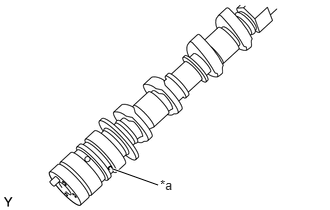
| *a | Advance Port |
Cover one of the 2 advance ports with your finger.
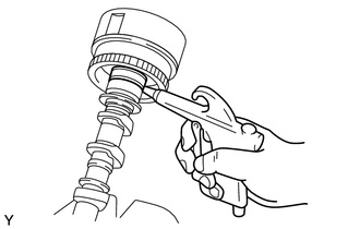
Apply air pressure to the other advance port.
- NOTICE:
-
Be careful of oil splashes.
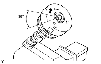
Check that the lock pin is released and the timing sprocket moves smoothly within a 30° range by hand.
- NOTICE:
-
The timing sprocket is locked in the most retarded position.
Lock the timing sprocket in the most retarded position, then remove the bolt and timing sprocket.
13523
4.INSPECT CAMSHAFT TIMING GEAR OR SPROCKET
Check the camshaft timing gear or sprocket for any wear or damage. If any, replace them with new ones.
13566B
5.INSPECT TIMING CHAIN GUIDE
Check the timing chain guide for any wear or damage. If any, replace them with new ones.
13591
6.INSPECT TIMING CHAIN TENSION ARM
Check the timing chain tension arm for any wear or damage. If any, replace them with new ones.
11101A
7.INSPECT CYLINDER HEAD SET BOLT
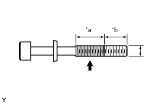
| *a | 25 mm (0.9843 in.) |
| *b | 20 mm (0.7874 in.) |
Using a micrometer, measure the thread diameter at several positions as indicated in the illustration.
- Minimum bolt diameter:
8.75 mm (0.3445 in.)
If the thread diameter is less than the minimum, replace the cylinder head set bolt.
8.INSPECT CAMSHAFT
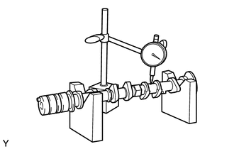
Inspect the circle runout.
Place the camshaft on V-blocks.
Using a dial indicator, measure the concentricity of the camshaft at the center journal.
- Maximum circle runout:
0.03 mm (0.0012 in.)
If the circle runout is greater than the maximum, replace the camshaft.
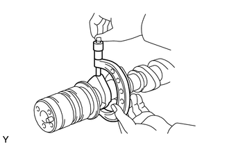
Inspect the cam lobe height.
Using a micrometer, measure the cam lobe height.
- Standard cam lobe height:
- Camshaft:
40.38 to 40.52 mm (1.5898 to 1.5953 in.)
- No. 2 Camshaft:
39.89 to 40.03 mm (1.5705 to 1.5760 in.)
If the cam lobe height is not as specified, replace the camshaft.
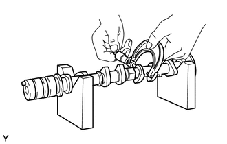
Inspect the cam journal diameter.
Using a micrometer, measure the cam journal diameter.
| Camshaft | No. 2 Camshaft | |
|---|---|---|
| No. 1 journal | 33.984 to 34.000 mm
(1.3380 to 1.3386 in.) |
25.979 to 25.995 mm
(1.0228 to 1.0234 in.) |
| No. 2 - No. 5 journal | 22.979 to 22.995 mm
(0.9047 to 0.9053 in.) |
22.979 to 22.995 mm
(0.9047 to 0.9053 in.) |
If the cam journal diameter is not as specified, inspect the oil clearance.
9.INSPECT CAMSHAFT THRUST CLEARANCE
Set the No. 2 camshaft and camshaft to the cylinder head.
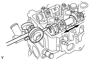
Using a dial indicator, measure the thrust clearance of each camshaft (while moving the camshaft back and forth).
- Standard thrust clearance:
0.10 to 0.24 mm (0.0039 to 0.0095 in.)
If the thrust clearance is not as specified, replace the cylinder head. If the thrust of the camshaft is scratched, replace the camshaft, as well.
10.INSPECT CAMSHAFT OIL CLEARANCE
Clean the camshaft and bearing cap.
Set the camshaft on the cylinder head.
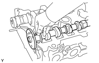
Lay a strip of Plastigage across the camshaft journal.
Install the camshaft bearing cap.
- Torque:
- 13 N*m (127 kgf*cm, 9 ft.*lbf)
- NOTICE:
-
Do not turn the camshaft when measuring.
Remove the bearing cap.
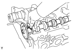
Measure the Plastigage at its widest point.
| Camshaft | Camshaft No. 2 | |
|---|---|---|
| No. 1 journal | 0.025 to 0.061 mm
(0.0010 to 0.0024 in.) |
0.037 to 0.073 mm
(0.0015 to 0.0029 in.) |
| No. 2 - No. 5 journal | 0.037 to 0.073 mm
(0.0015 to 0.0029 in.) |
0.037 to 0.073 mm
(0.0015 to 0.0029 in.) |
- Maximum oil clearance:
0.10 mm (0.0039 in.)
If the width is greater than the maximum, replace the cylinder head.
- NOTICE:
-
Completely remove the Plastigage after the measurement.