K3-VE ENGINE MECHANICAL CYLINDER HEAD REASSEMBLY
PROCEDURE

 1.INSTALL TIGHT PLUG
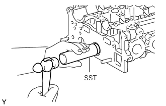
Apply adhesive to the outer surface of a new tight plug.
- Adhesive:
Toyota Genuine Adhesive 1324, Three Bond 1324 or equivalent
Using SST, install the tight plug until its height is as illustrated.
- Standard depth:
0.1 to 1.0 mm (0.004 to 0.039 in.)
- SST
- 09950-60010 (09951-00220, 09951-00260)
09950-70010 (09951-07100)
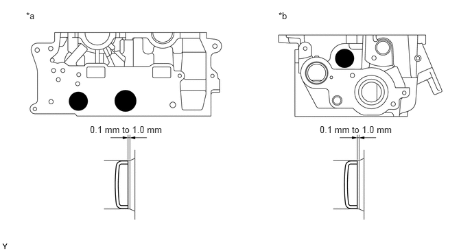
| *a | Front Side View | *b | Rear Side View |
2.INSTALL RING WITH HEAD PIN
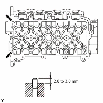
Using a plastic-faced hammer, tap in new ring pins until its protrusion height is as specified.
- Protrusion height:
2.0 to 3.0 mm (0.079 to 0.118 in.)
3.INSTALL STUD BOLT
Install the stud bolts in the positions shown in the illustration.
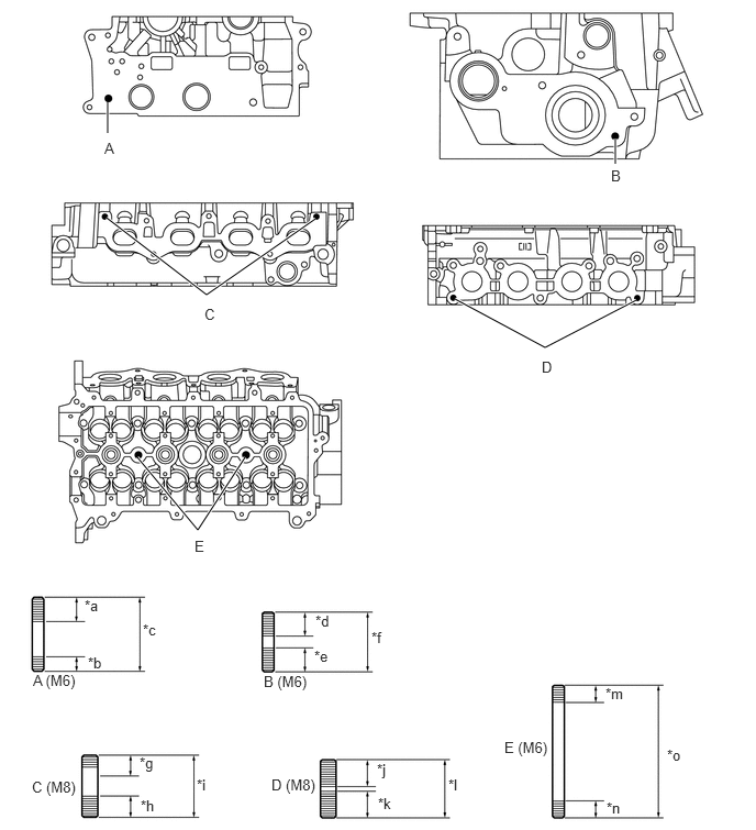
| *a | 12 mm (0.4724 in.) | *b | 7 mm (0.2756 in.) * |
| *c | 37 mm (1.4567 in.) | *d | 12 mm (0.4724 in.) |
| *e | 12 mm (0.4724 in.) | *f | 30 mm (1.1811 in.) |
| *g | 12 mm (0.4724 in.) | *h | 12 mm (0.4724 in.) |
| *i | 37 mm (1.4567 in.) | *j | 13.5 mm (0.5315 in.) |
| *k | 13.5 mm (0.5315 in.) | *l | 29 mm (1.1417 in.) |
| *m | 9 mm (0.3543 in.) | *n | 9 mm (0.3543 in.) |
| *o | 66.9 mm (2.6339 in.) | - | - |
*: Cylinder head side
- Torque:
- A,B,E : 4.0 N*m (41 kgf*cm, 35 in.*lbf)
- C,D : 5.0 N*m (51 kgf*cm, 44 in.*lbf)
4.INSTALL UNION
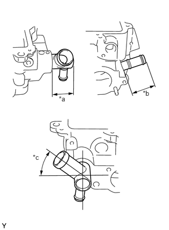
| *a | 45.2 to 47.2 mm (1.7795 to 1.8583 in.) |
| *b | 42 to 44 mm (1.6535 to 1.7323 in.) |
| *c | 31°+/-5°(w/ heater) 49°+/-5°(w/o heater) |
Apply adhesive to the inside of the holes in the cylinder head.
- Adhesive:
Toyota Genuine Adhesive 1324, Three Bond 1324 or equivalent
Using a press, press in a new union until its height is as illustrated.
- NOTICE:
- ·
Install the union within 3 minutes of applying the adhesive.
·Do not expose the adhesive to coolant for at least 1 hour after installation.
5.INSTALL VALVE SEAT
13711A
6.INSTALL VALVE STEM OIL O SEAL OR RING
Apply a light coat of engine oil to the lip of a new valve stem oil o seal or ring.
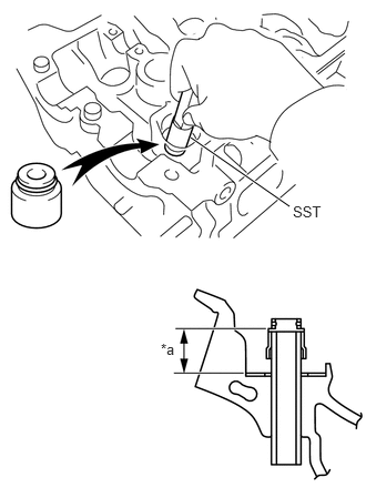
| *a | 14.2 to 15.8 mm (0.5591 to 0.6220 in.) |
Using SST, install the valve stem oil o seal or ring.
- SST
- 09201-41020
- HINT:
-
After pressing in the oil seal, check that the height of the valve stem valve stem oil o seal or ring is as illustrated.
7.INSTALL VALVE
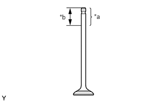
| *a | Valve Tip |
| *b | 20 mm (0.7874 in.) |
Apply engine oil to the valve tip.
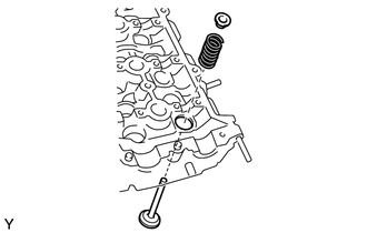
Install the valve, valve spring and retainer onto the cylinder head.
- NOTICE:
-
Install the parts onto their original locations.
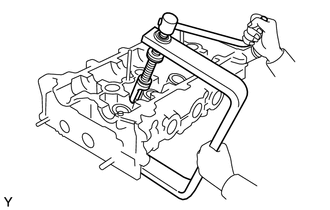
Using SST, install the retainer lock.
- SST
- 09202-70020 (09202-01010, 09202-01020, 90154-80004)
09202-00020
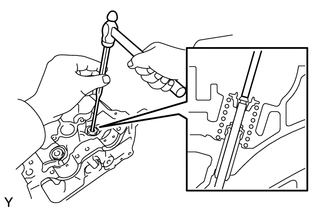
Using a 5 mm pin punch, tap in the valve tip so that the valve spring becomes stable.
- NOTICE:
-
Be careful not to damage the tip of the valve stem.
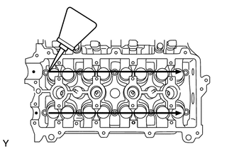
After installing all the valve springs, apply engine oil as illustrated.
15678A
8.INSTALL OIL CONTROL VALVE FILTER
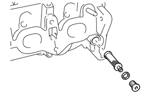
Using an 8 mm socket hexagon wrench, place a new gasket on the plug and install the oil control valve filter.
- Torque:
- 25 N*m (250 kgf*cm, 18 ft.*lbf)
13751
9.INSTALL VALVE LIFTER
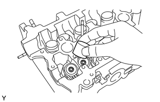
Apply a light coat of engine oil to the valve lifter.
- NOTICE:
-
Install the parts onto their original locations.
Install the valve lifter onto the cylinder head.
Check that the valve lifter turns smoothly.