K3-VE ENGINE MECHANICAL CYLINDER BLOCK REASSEMBLY
PROCEDURE

 1.INSTALL TIGHT PLUG
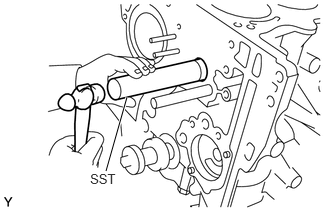
Apply adhesive to the outer surface of a new tight plug.
- Adhesive:
Toyota Genuine Adhesive 1324, Three Bond 1324 or equivalent
Using SST, install the tight plug until its height is as illustrated.
- Standard depth:
- Tight plug A:
-0.3 to 1.2 mm (-0.012 to 0.047 in.)
- Tight plug B:
5.25 to 6.75 mm (0.207 to 0.266 in.)
- Tight plug C:
-0.6 to 0.9 mm (-0.024 to 0.035 in.)
- SST
- 09950-60010 (09951-00220, 09951-00270)
09950-70010 (09951-07100)
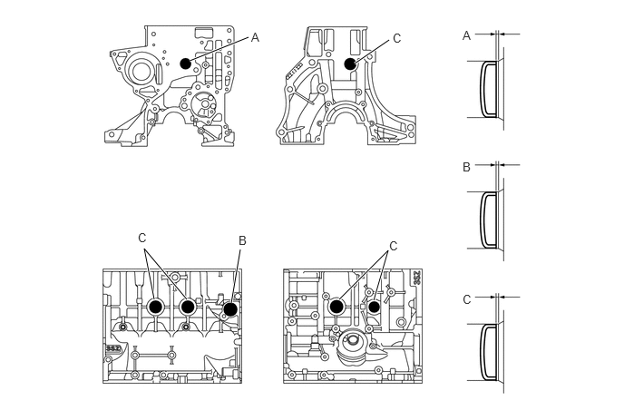
- Specification:
Area Measurement A -0.3 to 1.2 mm (-0.0118 to 0.0472 in.) B 5.25 to 6.75 mm (0.2067 to 0.2657 in.) C -0.6 to 0.9 mm (-0.0236 to 0.0354 in.)
2.INSTALL STUD BOLT
Install the stud bolts in the positions shown in the illustration.
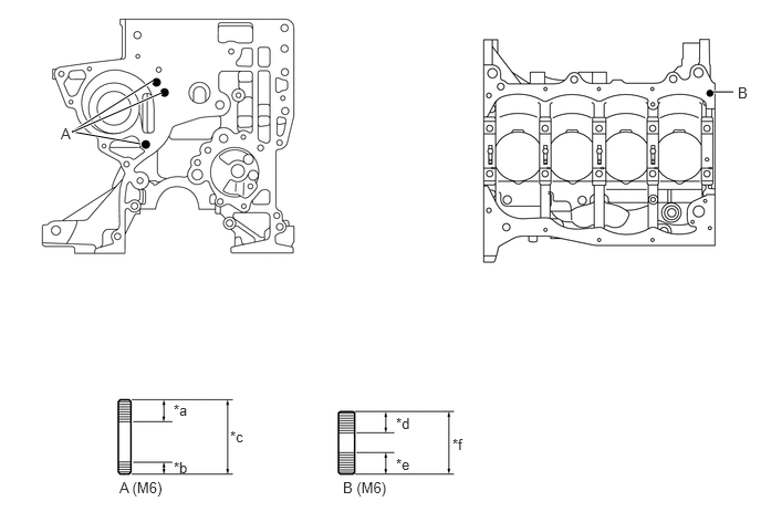
| *a | 12 mm (0.4724 in.) | *b | 7 mm (0.2756 in.) * |
| *c | 37 mm (1.4567 in.) | *d | 9 mm (0.3543 in.) |
| *e | 9 mm (0.3543 in.) | *f | 23 mm (0.9055 in.) |
*: Cylinder block side
- Torque:
- Bolt A,B : 4.0 N*m (41 kgf*cm, 35 in.*lbf)
15310J
3.INSTALL OIL REGULATOR ASSEMBLY
Install the oil regulator into the cylinder block.
- Torque:
- 40 N*m (408 kgf*cm, 30 ft.*lbf)
4.INSTALL DRAIN COCK PLUG
Apply adhesive to the threads.
- Adhesive:
Toyota Genuine Adhesive 1324, Three Bond 1324 or equivalent
Install the water drain cock onto the cylinder block.
- Torque:
- 30 N*m (306 kgf*cm, 22 ft.*lbf)
- NOTICE:
- ·
Install the water drain cock within 3 minutes of applying the adhesive.
·Do not expose the adhesive to coolant for at least 1 hour after installation.
5.INSTALL CRANKSHAFT BEARING
13411
6.INSTALL CRANKSHAFT
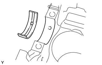
Install the 5 upper bearings.
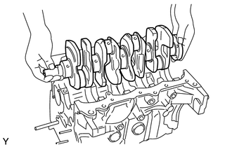
Apply engine oil to the sliding surface with the crankshaft on the upper bearing. Install the crankshaft into the cylinder block.
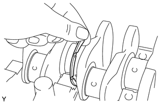
Insert the claw-less side of the crankshaft thrust washer, then install the washer with the oil groove facing outward (the crank side).
- NOTICE:
-
Before installing, apply engine oil to the oil groove.
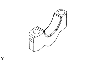
Align the lower bearing claw with the lock groove of the bearing cap, then install the upper bearing.
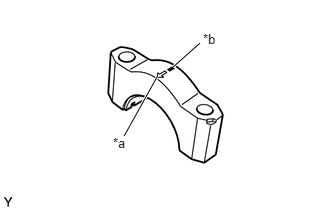
| *a | Front Mark |
| *b | Number |
Install the 5 lower bearings.
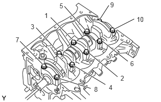
Apply a light coat of engine oil to the threads and seating surfaces of the bolts. Temporarily tighten the bolts in several steps in the sequence shown in the illustration, then retighten the bolts to the specified torque.
- Torque:
- 59 N*m (602 kgf*cm, 44 ft.*lbf)
- NOTICE:
-
Check that the crankshaft turns smoothly while tightening the bolts.
7.INSTALL PISTON SUB-ASSEMBLY WITH PIN
Apply engine oil to the piston pin and the pin hole in the connecting rod.
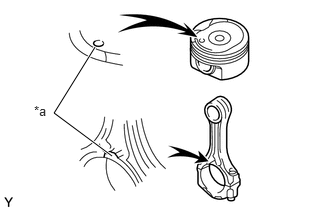
| *a | Front Mark |
Align the front mark of the piston and the front mark of the connecting rod.
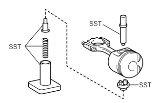
Using SST and a press, press into the piston pin.
- SST
- 09221-25026 (09221-00021, 09221-00030, 09221-00130, 09221-00050, 09221-00170)
09221-00240
- NOTICE:
- ·
Press in the piston pin from the front mark side of the piston.
·Press in the piston pin straight downward. Do not press it at an angle.
·Do not change the combinations of the pistons and piston pins.
13041
8.INSTALL CONNECTING ROD BEARING
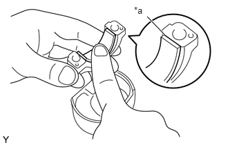
| *a | Claw |
Align the bearing claw and oil groove, then install the bearing onto the connecting rod and connecting rod cap.
13011
9.INSTALL PISTON RING SET
- HINT:
-
If reusing the piston rings, install them in the same combination with the surfaces facing correctly.
Install the oil ring set by hand.
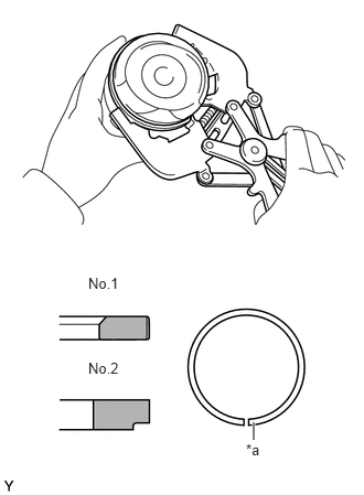
| *a | Identification Mark |
Using a piston pin expander, install the compression ring with the identification mark facing upward.
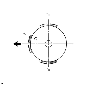
| *a | No. 1 Compression and Upper Side Rail |
| *b | Expander |
| *c | No. 2 Compression and Upper Side Rail |

|
Engine Front |
Adjust the piston ring so that its gap is located as illustrated.
10.INSTALL PISTON SUB-ASSEMBLY WITH CONNECTING ROD
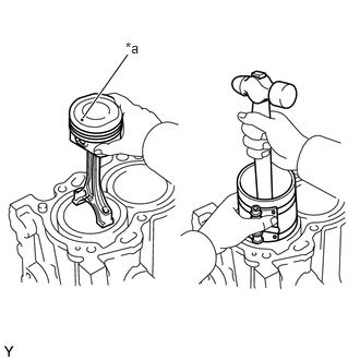
| *a | Front Mark |
Apply engine oil to the cylinder walls, pistons and surfaces of the connecting rod bearings.
Check that the gap of the piston ring is located correctly.
Check the front marks. Using a piston ring compressor, install the piston with connecting rod into the cylinder block.
- NOTICE:
-
Keep the same combinations of the pistons and cylinders as before dissembling.
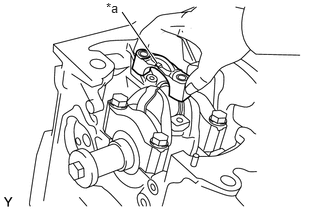
| *a | Front Mark |
Check that the connecting rod and its cap are in the correct combination and that the front marks are facing correctly, then install the connecting rod cap onto the connecting rod.
Apply a light coat of engine oil to the threads and seating surfaces of the bolts.
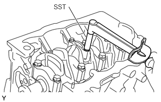
Using SST, temporarily tighten the bolts in several steps, then retighten the bolts to the specified torque.
- SST
- 09205-16011
- Torque:
- 22 N*m (224 kgf*cm, 16 ft.*lbf)
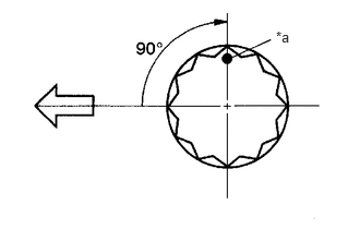
| *a | Paint Mark |

|
Engine Front |
Mark the front of the bolts with paint.
Retighten the bolts by an additional 90°.
Check that the crankshaft turns smoothly.