RM19Y0E
_51
Engine / Hybrid System
_002974
K3-VE EMISSION CONTROL
_0015034
PURGE VALVE
G
K3-VE EMISSION CONTROL PURGE VALVE INSPECTION
PROCEDURE

 25860
1.INSPECT NO. 1 VACUUM SWITCHING VALVE ASSEMBLY
a.
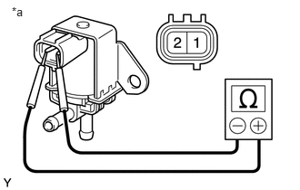
Check the resistance.
i.
0.135,0.052 0.323,0.229
0.188,0.177
10
*a
| *a | Component without harness connected
(Purge Valve) |
Measure the resistance according to the value(s) in the table below.
- Standard resistance:
Tester Connection Condition Specified Condition 1-2 20°C (68°F) 30 to 34 Ω
If the resistance is not as specified, replace the No. 1 vacuum switching valve assembly.
b.
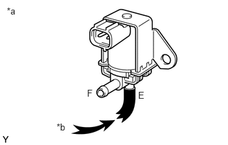
Check the operation.
i.
0.854,1.833 1.052,1.99
0.198,0.156
10
*b
0.104,0.083 0.302,0.24
0.198,0.156
10
*a
1.313,1.323 1.448,1.49
0.135,0.167
10
F
2.083,1.354 2.208,1.521
0.125,0.167
10
E
| *a | Component without harness connected
(Purge Valve) |
| *b | Air |
Check that air does not flow from port E to port F.
ii.
1.49,1.365 1.615,1.51
0.125,0.146
10
E
0.802,1.208 0.917,1.354
0.115,0.146
10
F
0.104,0.063 0.313,0.24
0.208,0.177
10
*a
0.354,1.542 0.563,1.719
0.208,0.177
10
*b
| *a | Component without harness connected
(Purge Valve) |
| *b | Air |
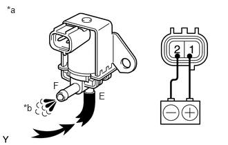
Apply battery voltage across the terminals to check that air flows from port E to port F.
iii.
Check that air flows from port E to port F.
If the operation is not as specified, replace the No. 1 vacuum switching valve assembly.