3SZ-VE STARTING STARTER(for Manual Transmission) REASSEMBLY
PROCEDURE

 28199A
1.INSTALL DUST STARTER PROTECTOR
28011
2.INSTALL STARTER CLUTCH SUB-ASSEMBLY
Apply grease to the starter clutch sub-assembly bushing, spline and starter pinion stop nut (inner).
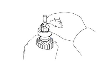
Install the starter clutch sub-assembly and starter pinion stop nut (inner) onto the starter armature assembly.
Apply grease to a new snap ring, then install it onto the starter armature assembly groove.
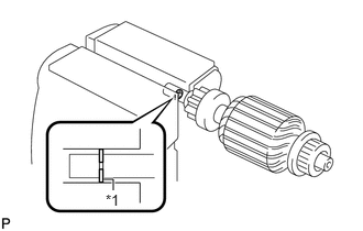
| *1 | Snap Ring |
Compress the snap ring using a vise.
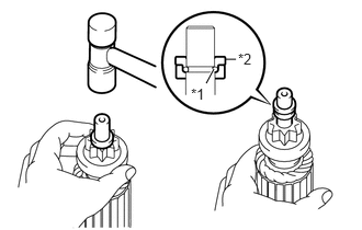
| *1 | Snap Ring |
| *2 | Starter Pinion Stop Nut (inner) |
While holding the starter clutch sub-assembly by hand, slightly tap the starter armature assembly shaft tip with a plastic faced hammer until the starter pinion stop nut (inner) fits over the snap ring.
Install the starter pinion stop nut (outer).
28120
3.INSTALL STARTER YOKE ASSEMBLY
Clamp the starter armature assembly shaft in a vise.
- NOTICE:
-
Do not clamp it in a vise too tightly.
Install the starter yoke assembly onto the starter armature assembly.
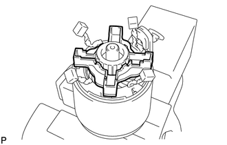
Install the starter brush holder assembly.
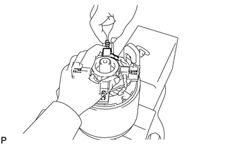
Install the 4 brush springs.
- NOTICE:
-
Do not allow the brush springs to fly off.
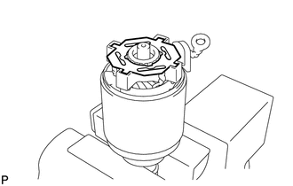
Install the brush holder insulator.
Install the starter commutator end flame assembly.
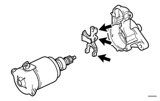

|
Grease |
Apply grease to the contact surfaces of the starter pinion drive lever, housing, clutch and plunger.
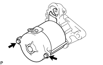
Install the starter yoke assembly and starter pinion drive lever onto the starter drive housing with the 2 through bolts.
- Torque:
- 5.9 N*m (60 kgf*cm, 52 in.*lbf)
28150
4.INSTALL MAGNET STARTER SWITCH ASSEMBLY
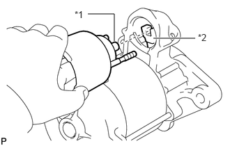
| *1 | Plunger |
| *2 | Magnet Starter Switch Assembly |
Place the plunger in place on the starter pinion drive lever, then install the magnet starter switch assembly.
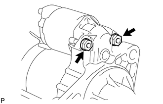
Install the 2 nuts.
- Torque:
- 8.3 N*m (85 kgf*cm, 74 in.*lbf)
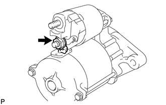
Install the lead wire onto the magnet starter switch assembly terminal with the nut.
- Torque:
- 9.8 N*m (100 kgf*cm, 87 in.*lbf)