K3-VE STARTING STARTER(for Automatic Transmission) INSPECTION
PROCEDURE

 28150
1.INSPECT MAGNET STARTER SWITCH ASSEMBLY
Check the plunger.
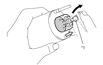
| *1 | Plunger |
Push the plunger and release it. Check that the plunger returns to its original position quickly.
If the result is not as specified, replace the magnet starter switch assembly.
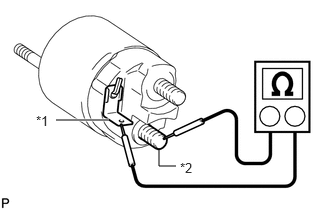
| *1 | Terminal 50 |
| *2 | Terminal C |
Check if the pull-in coil has an open circuit.
Measure the resistance between terminals 50 and C.
- Standard Resistance:
Tester Connection Condition Specified Condition Terminal 50 - Terminal C Always Below 1 Ω
If the result is not as specified, replace the magnet starter switch assembly.
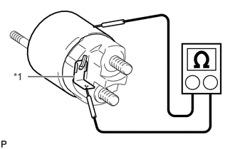
| *1 | Terminal 50 |
Check if the holding coil has an open circuit.
Measure the resistance between terminal 50 and the switch body.
- Standard Resistance:
Tester Connection Condition Specified Condition Terminal 50 - Body Always Below 2 Ω
If the result is not as specified, replace the magnet starter switch assembly.
28160
2.INSPECT STARTER ARMATURE ASSEMBLY
Check the surface of the commutator for dirt and burns. If the surface is dirty or burnt, correct it with sandpaper (No. 400) or a lathe. If necessary, replace the starter armature assembly.
Inspect the commutator for an open circuit.
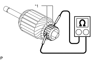
| *1 | Segment |
Measure the resistance according to the value(s) in the table below.
- Standard Resistance:
Tester Connection Condition Specified Condition Segment - Segment Always Below 1 Ω
If the result is not as specified, replace the starter armature assembly.
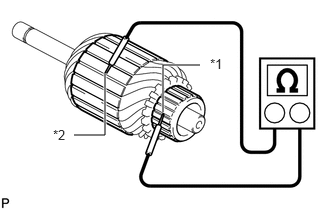
| *1 | Segment |
| *2 | Armature Coil Core |
Inspect the commutator for a short circuit.
Measure the resistance according to the value(s) in the table below.
- Standard Resistance:
Tester Connection Condition Specified Condition Segment - Armature coil core Always 10 kΩ or higher
If the result is not as specified, replace the starter armature assembly.
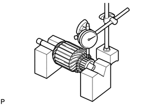
Inspect the commutator circle runout.
Place the starter armature assembly on V-blocks.
Using a dial gauge, measure the circle runout.
- Maximum circle runout:
0.4 mm (0.016 in.)
If the circle runout is more than the maximum, replace the starter armature assembly.
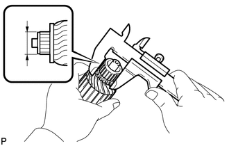
Using a vernier caliper, measure the commutator diameter.
- Standard diameter:
28 mm (1.102 in.)
- Minimum diameter:
27 mm (1.063 in.)
If the diameter is less than the minimum, replace the starter armature assembly.
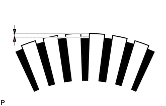
Check that the undercut portion is clean and free of foreign matter. Smooth out the edge.
- Standard undercut depth:
0.6 mm (0.024 in.)
- Minimum undercut depth:
0.2 mm (0.008 in.)
If the undercut depth is less than the minimum, correct it with a hacksaw blade.
28011
3.INSPECT STARTER CLUTCH SUB-ASSEMBLY
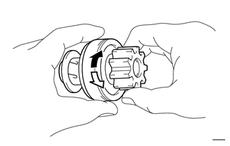
Check the starter clutch sub-assembly operation.

|
Free |

|
Lock |
Grip the clutch in one hand and turn only the inner sleeve with the other hand.
Check that the inner sleeve turns easily in the "free" direction but cannot turn in the "lock" direction as shown in the illustration. If the starter clutch sub-assembly does not operate as specified, replace the starter clutch sub-assembly.
28120
4.INSPECT STARTER YOKE ASSEMBLY
Inspect the starter yoke assembly.
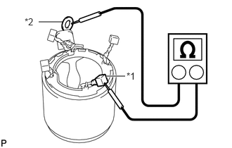
| *1 | Brush |
| *2 | Lead Wire |
Measure the resistance according to the value(s) in the table below.
- Standard Resistance:
Tester Connection Condition Specified Condition Brush - Lead wire Always Below 1 Ω
If the result is not as specified, replace the starter yoke assembly.
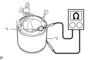
| *1 | Brush |
| *2 | Starter Yoke Body |
Measure the resistance according to the value(s) in the table below.
- Standard Resistance:
Tester Connection Condition Specified Condition Brush - Starter yoke body Always 10 kΩ or higher
If the result is not as specified, replace the starter yoke assembly.
28142
5.INSPECT STARTER BRUSH
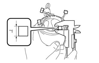
| *1 | Length |
Using vernier calipers, measure the starter brush length.
- Standard length:
10 mm (0.40 in.)
- Minimum length:
6 mm (0.24 in.)
If the brush length is less than the minimum, replace the brush.
28142
6.REPLACE STARTER BRUSH
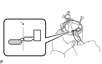
| *a | Cut |
Cut the brush lead wire on the terminal side.
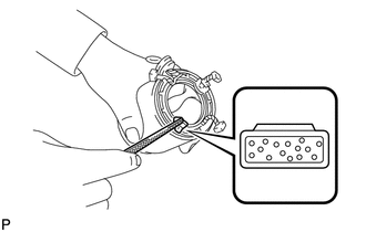
Smooth the brush lead wire using a file.
- NOTICE:
-
Only a small area can be filed. Do not damage the starter yoke assembly.
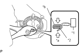
| *1 | Brush |
| *2 | Plate |
| *a | Press |
| *b | Weld Side |
Using pliers, pinch the starter plate of the brush (service part) on the weld side of the terminal lead wire and apply force to it.
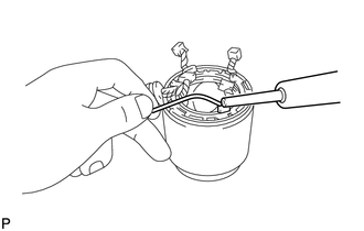
Apply solder to the contact surface.
- HINT:
- ·
Heat the contact surface well. Apply a sufficient amount of solder to the inside of the plate while paying attention not to apply it to the lead wire.
·Do not apply solder to the starter yoke assembly.