A4Q AUTOMATIC TRANSMISSION / TRANSAXLE AUTOMATIC TRANSMISSION SYSTEM P0722 Output Speed Sensor Circuit No Signal P2767 Input / Turbine Speed Sensor "B" Circuit No Signal
DESCRIPTION
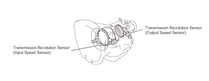
The input speed sensor and the output speed sensor are installed on the case side face. The rotational sensor adopts the magnetic type rotational sensor that applies to the hall element to detect the number of revolutions accurately.
The input speed sensor detects the number of revolutions of the front clutch drum (the number of the sensor rotor teeth is 30).
The output speed sensor detects the number of revolutions of the output shaft (the number of the sensor rotor teeth is 20).
| DTC No. | Detection Item | DTC Detection Condition | Trouble Area | MIL | Warning Indicate | Memory |
|---|---|---|---|---|---|---|
| P0722 | Output Speed Sensor Circuit No Signal | Under the condition of (a) or (b), the code is output.
(2 trip detection logic) (a) While driving, the output speed suddenly becomes 0. Or, the ratio with the turbine speed is abnormal (sensor system is open or short). (b) The C2 clutch cannot be engaged, which causes the vehicle not to start (only the turbine speed increases). (Trouble in automatic transmission assembly) |
·
Open or short in transmission revolution sensor (output speed sensor) circuit ·
Transmission revolution sensor (output speed sensor) ·
Open or short in park/neutral position switch circuit ·
TCM ·
Valve body assembly ·
Automatic Transmission Assembly |
Come on | Blinks | DTC stored |
| P2767 | Input / Turbine Speed Sensor "B" Circuit No Signal | Under the condition of (a) or (b), the code is output.
(2 trip detection logic) (a) When the engine speed is not 0 and turbine speed is 0 for a period of time while the vehicle stops in P or N position. (b) While driving when the shift lever not in P or N, the turbine speed (or revolution) is 0. |
·
Open or short in transmission revolution sensor (input speed sensor) circuit ·
Transmission revolution sensor (input speed sensor) ·
Open or short in park/neutral position switch circuit ·
TCM |
Come on | Blinks | DTC stored |
MIL:"Comes on" means the MIL (Malfunction IndicatorLamp) illuminates.
Memory:"DTC stored" means the TCM stores the trouble code if the ECU detects the DTC detection condition.
WIRING DIAGRAM
PROCEDURE
Connect the intelligent tester to the DLC3.
Turn the ignition switch to ON.
Turn the tester on.
Shift the shift lever to the P, N and D.
Enter the following menus: Powertrain / ECT / DTC / Current or Pending.
- Powertrain > ECT > Trouble Codes
- 50001 565
Check if diagnosis code P0705 is output.
- HINT:
-
When not using the intelligent tester, refer to DTC CHECK / CLEAR.
-
Click hereDrivetrain>A4Q AUTOMATIC TRANSMISSION / TRANSAXLE>AUTOMATIC TRANSMISSION SYSTEM>DTC CHECK / CLEAR
- Result:
proceed to YES NO
YES
NO
Remove the transmission revolution sensor (input speed sensor) and transmission revolution sensor (output speed sensor) from the transmission.
Swap the transmission revolution sensor (input speed sensor) for the transmission revolution sensor (output speed sensor).
- NOTICE:
-
Be sure to swap the sensors.
Clear the DTC, and check for the DTC again after conducting the running test.
- Powertrain > ECT > Clear DTCs
- 50002 565
- Powertrain > ECT > Trouble Codes
- 50001 565
- HINT:
-
When not using the intelligent tester, refer to DTC CHECK / CLEAR.
-
Click hereDrivetrain>A4Q AUTOMATIC TRANSMISSION / TRANSAXLE>AUTOMATIC TRANSMISSION SYSTEM>DTC CHECK / CLEAR
- Result:
Display (DTC Output) Proceed to DTC same as when vehicle brought in P2767 → P2767 A DTC same as when vehicle brought in P0722 → P0722 B DTC different from when vehicle brought in P0722 → P2767 C DTC different from when vehicle brought in P2767 → P0722 D
A
B
C
D
Disconnect the E20 transmission revolution sensor (input speed sensor) connector.
Disconnect the E10 TCM connector.
Measure the resistance according to the value(s) in the table below.
- Standard Resistance (Check for Open):
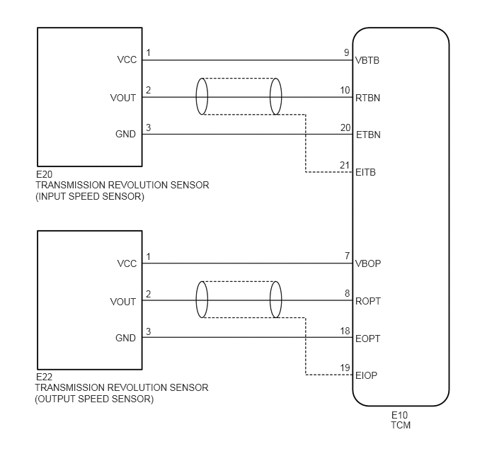
Tester Connection Condition Specified Condition E20-1 (VCC) - E10-9 (VBTB) Always Below 1 Ω E20-2 (VOUT) - E10-10 (RTBN) Always Below 1 Ω E20-3 (GND) - E10-20 (ETBN) Always Below 1 Ω
- Standard Resistance (Check for Short):
Tester Connection Condition Specified Condition E10-10 (RTBN) - Body ground Always 10 kΩ or higher
Reconnect the E20 transmission revolution sensor (input speed sensor) connector.
Reconnect the E10 TCM connector.
- Result:
Proceed to OK NG
OK
NG
Disconnect the E22 transmission revolution sensor (output speed sensor) connector.
Disconnect the E10 TCM connector.
Measure the resistance according to the value(s) in the table below.
- Standard Resistance (Check for Open):
Tester Connection Condition Specified Condition E22-1 (VCC) - E10-7 (VBOP) Always Below 1 Ω E22-2 (VOUT) - E10-8 (ROPT) Always Below 1 Ω E22-3 (GND) - E10-18 (EOPT) Always Below 1 Ω
- Standard Resistance (Check for Short):
Tester Connection Condition Specified Condition E10-8 (ROPT) - Body ground Always 10 kΩ or higher
Reconnect the E22 transmission revolution sensor (output speed sensor) connector.
Reconnect the E10 TCM connector.
- Result:
Proceed to OK NG
OK
NG