A4Q AUTOMATIC TRANSMISSION / TRANSAXLE VALVE BODY ASSEMBLY REMOVAL
PROCEDURE

 1.DRAIN AUTOMATIC TRANSMISSION FLUID
Remove the drain plug and gasket, and drain the ATF.
Install a new drain plug with a new gasket.
- Torque:
- 25 N*m (250 kgf*cm, 18 ft.*lbf)
51202D
2.REMOVE FRONT LOWER SUSPENSION CROSSMEMBER SUB-ASSEMBLY
35103
3.REMOVE TRANSMISSION OIL LEVEL DIPSTICK SUB-ASSEMBLY
35106D
4.REMOVE AUTOMATIC TRANSMISSION OIL PAN SUB-ASSEMBLY
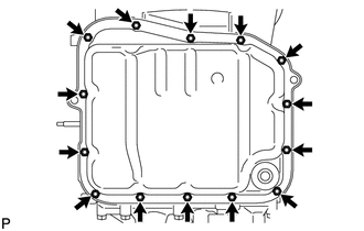
- NOTICE:
-
Some fluid will remain in the automatic transmission oil pan sub-assembly. Remove all automatic transmission oil pan sub-assembly bolts, and carefully remove the automatic transmission oil pan sub-assembly.
Remove the 14 bolts from the automatic transmission oil pan sub-assembly.
Tap on the circumference of the automatic transmission oil pan sub-assembly with a plastic hammer to remove it.
Remove any FIPG material on the contacting surface of transmission case.
33449E
5.REMOVE TRANSMISSION MAGNET
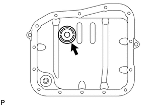
Remove the transmission magnet, and use it to collect steel particles.
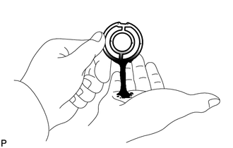
Carefully look at the foreign matter and particles in the automatic transmission oil pan sub-assembly and on the transmission magnet to anticipate the type of wear which might be found in the transmission.
- Result:
- Steel (magnetic):
bearing, gear and clutch plate wear
- Brass (non-magnetic):
bushing wear
35303B
6.REMOVE OIL STRAINER SUB-ASSEMBLY
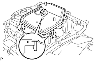
Disconnect the 3 claws and remove the oil strainer sub-assembly.
- NOTICE:
-
The oil strainer sub-assembly has 3 claws. Be careful not to break or bend them during removal.
- HINT:
-
Be sure to check whether the oil strainer sub-assembly mesh is clean.
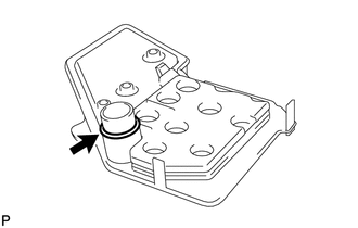
Remove the O-ring.
35409D
7.REMOVE MANUAL DETENT SPRING SUB-ASSEMBLY
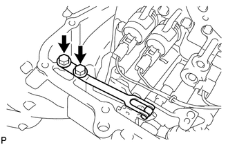
Remove the 2 bolts and manual detent spring sub-assembly.
- HINT:
-
Be sure to loosen the bolts evenly.
35410
8.REMOVE TRANSMISSION VALVE BODY ASSEMBLY
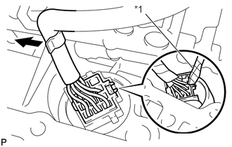
| *1 | Protective Tape |
Separate the solenoid wire assembly from the clamp of the transmission valve body assembly.
Using a screwdriver, disconnect the connector of the solenoid wire assembly.
- NOTICE:
-
Never pull out the wire itself directly when disconnecting the connector.
- HINT:
-
Tape up the screwdriver tip before use.
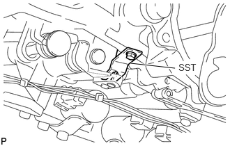
Support the manual valve idler shaft, using the following SST.
- SST
- 09350-97201
- NOTICE:
-
If the SST is not used, it will be difficult to perform reassembly of the transmission valve body assembly because the manual valve idler shaft will drop when the transmission valve body assembly is removed.
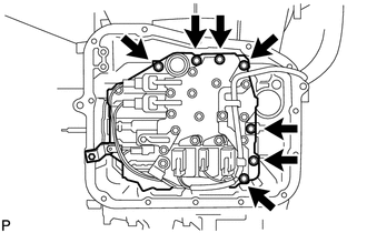
Remove the 7 bolts and transmission valve body assembly.
- HINT:
-
Be sure to remove the bolts evenly, removing opposing bolts in sequence.
35824
9.REMOVE BRAKE CYLINDER SEAL
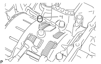
| *1 | Brake Cylinder Seal |
Remove the brake cylinder seal.