M5S MANUAL TRANSMISSION / TRANSAXLE MANUAL TRANSMISSION UNIT REASSEMBLY
PROCEDURE

 33257B
1.INSTALL GEAR OIL PLATE
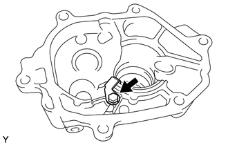
Install the gear oil plate with the bolt to the extension housing sub-assembly.
- Torque:
- 8.4 N*m (85 kgf*cm, 74 in.*lbf)
33103R
2.INSTALL MANUAL TRANSMISSION EXTENSION HOUSING OIL SEAL
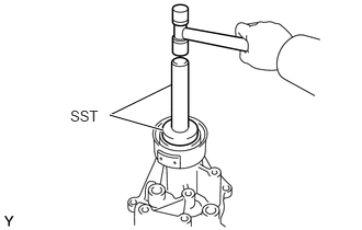
Using SST and a hammer, install a new manual transmission extension housing oil seal to the extension housing sub-assembly.
- SST
- 09950-60010 (09951-00540)
09950-70010 (09951-07150)
- Drive in depth:
0 to -0.5 mm (0 to -0.020 in.)
Coat the oil seal lip with MP grease.
33111Y
3.INSTALL TRANSMISSION CASE OIL SEAL
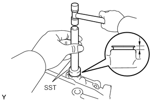
Using SST and a hammer, install the new transmission case oil seal to the manual transmission case.
- SST
- 09950-60010 (09951-00300)
09950-70010 (09951-07150)
- Protrusion :
3.9 to 4.7 mm (0.154 to 0.185 in.)
Coat the oil seal lip with MP grease.
33111Q
4.INSTALL CLUTCH HOUSING OIL SEAL
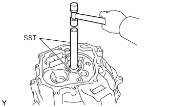
Using SST and a hammer, install the new clutch housing oil seal to the clutch housing.
- SST
- 09950-60010 (09951-00350)
09950-70010 (09951-07150)
Coat the oil seal lip with MP grease.
33256
5.INSTALL SELECT INNER LEVER
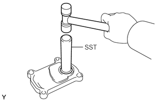
Using SST and a hammer, install the new oil seal to the control shaft cover.
- SST
- 09950-70010 (09951-07150)
Coat the oil seal lip with MP grease.
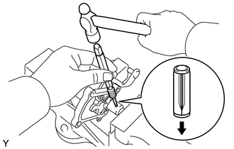
Install the select inner lever, select lever sub-assembly and spring to the control shaft cover.
Using a pin punch (5 mm) and hammer, install a new slotted spring pin.
- NOTICE:
-
Insert the slotted spring pin in the correct direction as shown in the illustration.
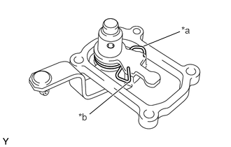
| *a | Short |
| *b | Long |
Install the spring as shown in the illustration.
33311
6.INSTALL INPUT SHAFT
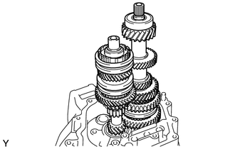
Coat the sliding and rotating surfaces of the input shaft and counter gear with manual transmission gear oil.
Install the input shaft and counter gear to the clutch housing.
33326
7.INSTALL BEARING LOCK PLATE
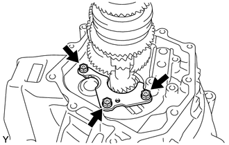
Install the bearing lock plate with the 3 bolts.
- Torque:
- 18 N*m (184 kgf*cm, 13 ft.*lbf)
33402
8.INSTALL REVERSE IDLER GEAR SUB-ASSEMBLY
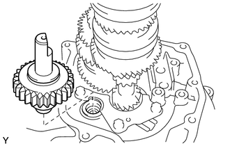
Install the reverse idler gear sub-assembly, reverse idler gear thrust washer and reverse idler gear shaft to the clutch housing.
33266C
9.INSTALL SHIFT INTER LOCK PLATE
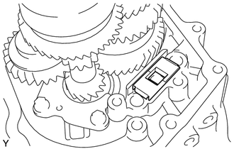
Install the 2 shift inter lock plates to the clutch housing.
33221
10.INSTALL REVERSE SHIFT ARM SUB-ASSEMBLY
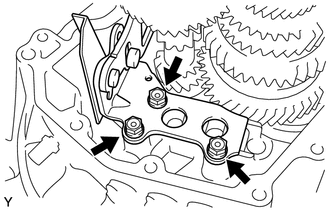
Install the reverse shift arm sub-assembly with the 3 bolts.
- Torque:
- 18 N*m (184 kgf*cm, 13 ft.*lbf)
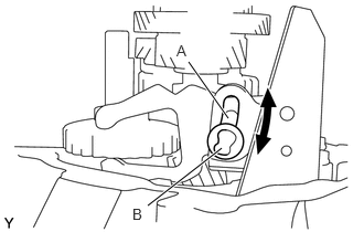
Ensure that the pin moves smoothly between positions A (neutral position) and B (5th gear position) with the idler gear fully lowered.
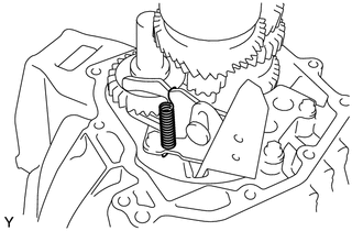
Install the spring to the reverse shift arm sub-assembly.
33243A
11.INSTALL NO. 2 GEAR SHIFT FORK SHAFT
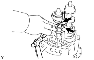
Install the No. 2 gear shift fork, No. 2 gear shift head and No. 2 gear shift fork shaft.
Using a pin punch (5 mm) and hammer, install the 2 new slotted spring pins to the No. 2 gear shift fork shaft.
33242
12.INSTALL NO. 1 GEAR SHIFT FORK SHAFT
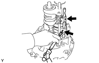
Install the No. 1 gear shift fork, No. 1 gear shift head and No. 1 gear shift fork shaft.
Using a pin punch (5 mm) and hammer, install the 2 new slotted spring pins to the No. 1 gear shift fork shaft.
33244D
13.INSTALL NO. 3 GEAR SHIFT FORK SHAFT
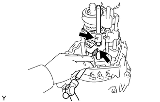
Install the No. 3 gear shift fork, reverse head and No. 3 gear shift fork shaft.
Using a pin punch (5 mm) and hammer, install the 2 new slotted spring pins to the No. 3 gear shift fork shaft.
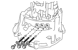
Install the 3 balls, springs and new gaskets to the clutch housing with the bolts.
- Torque:
- 25 N*m (255 kgf*cm, 18 ft.*lbf)
33321
14.INSTALL OUTPUT SHAFT
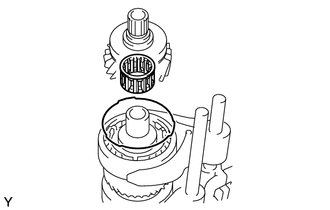
Coat the input shaft bearing with MP grease.
Install the input shaft bearing and the wave spring to the input shaft.
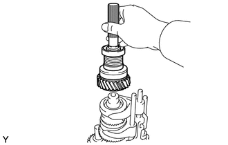
Install the output shaft onto the input shaft.
33111
15.INSTALL MANUAL TRANSMISSION CASE
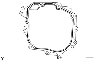

|
FIPG |
Apply FIPG to the manual transmission case, as shown in the illustration.
- FIPG:
Toyota Genuine Seal Packing 1281, Three Bond 1281 or equivalent
- NOTICE:
-
Parts must be assembled within 10 minutes of application.
-
Otherwise, the packing (FIPG) material must be removed and reapplied.
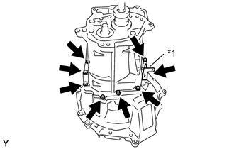
| *1 | Wire Harness Clamp Bracket |
Install the manual transmission case and wire harness clamp bracket with the 8 bolts.
- Torque:
- 18 N*m (184 kgf*cm, 13 ft.*lbf)
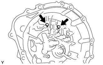
Install the 2 bolts to the clutch housing.
- Torque:
- 18 N*m (184 kgf*cm, 13 ft.*lbf)
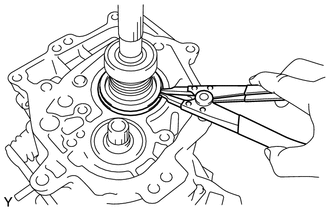
Using a snap ring expander, install the snap ring to the output shaft.
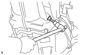
Using a hexagon socket wrench (6 mm), install a new gasket and the hexagon bolt to the reverse idler gear shaft.
- Torque:
- 25 N*m (255 kgf*cm, 18 ft.*lbf)
33203
16.INSTALL NO. 1 SHIFT LEVER SHAFT SUB-ASSEMBLY
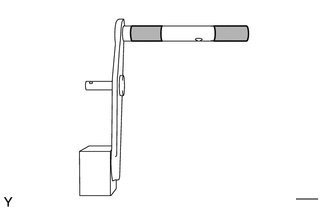

|
MP grease |
Coat the No. 1 shift lever shaft sub-assembly with MP grease.
Install the boot to the manual transmission case.
Install the No. 1 shift lever shaft and shift lever inner.
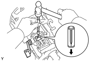
Using a pin punch (5 mm) and hammer, install a new slotted spring pin to the No. 1 shift lever shaft sub-assembly.
- NOTICE:
-
Insert the slotted spring pin in the correct direction as shown in the illustration.
33295A
17.INSTALL REVERSE RESTRICT SHAFT
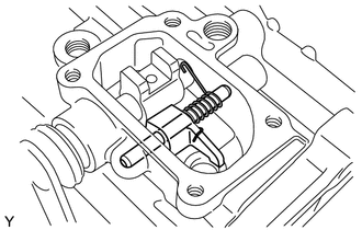
Install the spring, reverse restrict shaft and reverse restrict cam into the manual transmission case.
Install the spring as shown in the illustration.
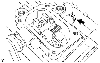
Install a new gasket and bolt.
- Torque:
- 25 N*m (255 kgf*cm, 18 ft.*lbf)
33284B
18.INSTALL REVERSE RESTRICT PIN HOLDER
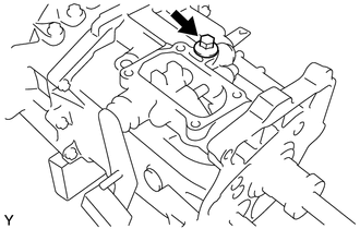
Install a new gasket and reverse restrict pin holder to the manual transmission case.
- Torque:
- 39 N*m (398 kgf*cm, 29 ft.*lbf)
33528B
19.INSTALL CONTROL SHAFT COVER
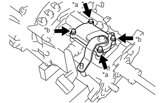
| *a | Standard |
| *b | Reamer |
Install the control shaft cover and a new gasket with the 4 bolts and 2 washers to the manual transmission case.
- Torque:
- 18 N*m (184 kgf*cm, 13 ft.*lbf)
- NOTICE:
-
There are two types of bolts: standard and reamer bolts.
-
Install them as shown in the illustration.
33151
20.INSTALL OUTPUT SHAFT REAR BEARING RETAINER
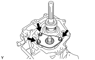
Install the output shaft rear bearing retainer with the 3 bolts.
- Torque:
- 18 N*m (184 kgf*cm, 13 ft.*lbf)
33323
21.INSTALL OUTPUT SHAFT OIL SLINGER
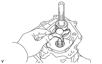
Install the output shaft oil slinger onto the manual transmission case.
33449B
22.INSTALL TRANSMISSION MAGNET
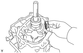
Install the transmission magnet onto the manual transmission case.
33103
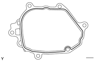
23.INSTALL EXTENSION HOUSING SUB-ASSEMBLY
|
|
FIPG |
Apply FIPG to the extension housing sub-assembly, as shown in the illustration.
- FIPG:
Toyota Genuine Seal Packing 1281, Three Bond 1281 or equivalent
- NOTICE:
-
Parts must be assembled within 10 minutes of application.
-
Otherwise, the packing (FIPG) material must be removed and reapplied.
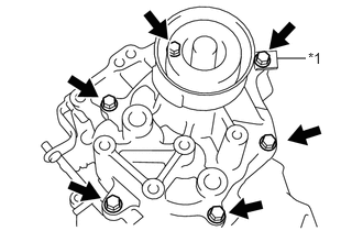
| *1 | Wire Harness Clamp Bracket |
Install the extension housing sub-assembly and wire harness clamp bracket with the 6 bolts.
- Torque:
- 37 N*m (377 kgf*cm, 27 ft.*lbf)
33283H
24.INSTALL DRAIN PLUG
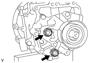
Install the drain plug and a new gasket to the extension housing sub-assembly.
- Torque:
- 39 N*m (398 kgf*cm, 29 ft.*lbf)
33283H
25.INSTALL FILLER PLUG
Install the filler plug and a new gasket to the extension housing sub-assembly.
- Torque:
- 39 N*m (398 kgf*cm, 29 ft.*lbf)
83181G
26.INSTALL SPEEDOMETER SENSOR (w/o ABS)
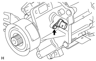
Install the speedometer sensor with the bolt to the extension housing sub-assembly.
- Torque:
- 8.4 N*m (85 kgf*cm, 74 in.*lbf)
33403S
27.INSTALL SPEEDOMETER SENSOR HOLE PLUG (w/ ABS)
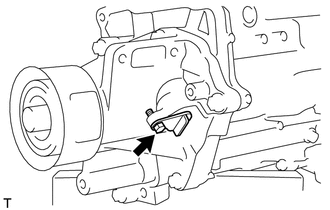
Install the new O-ring to the speedometer sensor hold plug.
Install the speedometer sensor hold plug with the bolt.
- Torque:
- 8.4 N*m (85 kgf*cm, 74 in.*lbf)
84210C
28.INSTALL BACK-UP LIGHT SWITCH ASSEMBLY
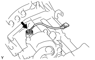
Install the back-up light switch assembly and a new gasket to the manual transmission case.
- Torque:
- 32 N*m (326 kgf*cm, 24 ft.*lbf)
Connect the back-up light switch assembly connector to the wire bracket.
31111B
29.INSTALL CLUTCH HOUSING PLUG
Install the clutch housing plug to the clutch housing.
- Torque:
- 8.4 N*m (85 kgf*cm, 74 in.*lbf)