M5S MANUAL TRANSMISSION / TRANSAXLE INPUT SHAFT INSPECTION
PROCEDURE

 33311
1.INSPECT INPUT SHAFT
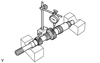
Using a dial indicator, check the input shaft for runout.
- Maximum runout:
0.015 mm (0.0006 in.)
If the runout exceeds the maximum, replace the input shaft.
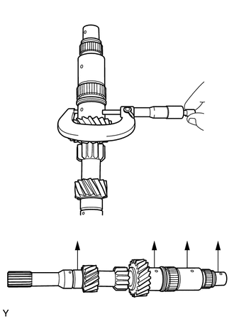
Using a micrometer, measure the outer diameter of the input shaft journal surface.
- Standard outer diameter:
- Part A:
25.002 to 25.017 mm (0.9843 to 0.9849 in.)
- Parts B and C:
31.971 to 31.991 mm (1.2587 to 1.2595 in.)
- Part D:
19.966 to 19.984 mm (0.7861 to 0.7868 in.)
- Minimum outer diameter:
- Part A:
25.002 mm (0.9843 in.)
- Parts B and C:
31.971mm (1.2587 in.)
- Part D:
19.966 mm (0.7860 in.)
If either outer diameter is less than the minimum, replace the input shaft.
33333
2.INSPECT 3RD GEAR SUB-ASSEMBLY
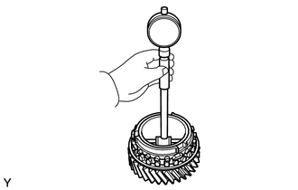
Using a cylinder gauge, measure the inside diameter of the 3rd gear sub-assembly.
- Standard inner diameter:
37.000 to 37.025 mm (1.4567 to 1.4577 in.)
- Maximum inner diameter:
37.025 mm (1.4577 in.)
If the inner diameter exceeds the maximum, replace the 3rd gear sub-assembly.
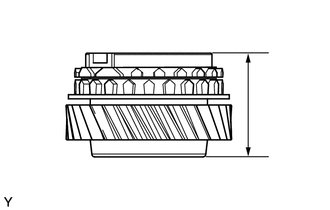
Using a vernier caliper, measure the height of the 3rd gear sub-assembly.
- Standard height:
37.92 to 37.98 mm (1.4929 to 1.4953 in.)
- Minimum height:
37.92 mm (1.4929 in.)
If the height is less than the minimum, replace the 3rd gear sub-assembly.
33336
3.INSPECT 5TH GEAR
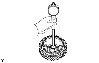
Using a cylinder gauge, measure the inside diameter of the 5th gear.
- Standard inner diameter:
37.000 to 37.025 mm (1.4567 to 1.4577 in.)
- Maximum inner diameter:
37.025 mm (1.4577 in.)
If the inner diameter exceeds the maximum, replace the 5th gear.
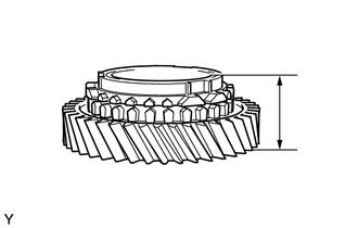
Using a vernier caliper, measure the height of the 5th gear.
- Standard height:
27.82 to 27.88 mm (1.0953 to 1.0976 in.)
- Minimum height:
27.82 mm (1.0953 in.)
If the height is less than the minimum, replace the 5th gear.
33367
4.INSPECT SYNCHRONIZER RING (for 3rd gear)
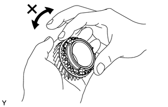
Coat the 3rd gear cone with manual transmission gear oil. Check the braking effect of the No. 1 synchronizer ring. Turn the No. 1 synchronizer ring in one direction while pushing it against the 3rd gear cone. Check that the ring locks.
If the braking effect is insufficient, apply a small amount of the fine lapping compound between the No. 1 synchronizer ring and 3rd gear cone. Lightly rub the No. 1 synchronizer ring and 3rd gear cone together.
- NOTICE:
-
Ensure the fine lapping compound is completely washed off after rubbing.
Check the braking effect of the No.1 synchronizer ring again.
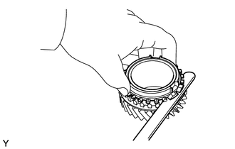
Using a feeler gauge, measure the clearance between the No. 1 synchronizer ring back and 3rd gear spline end.
- Standard clearance:
0.95 to 1.35 mm (0.0374 to 0.0531 in.)
- Minimum clearance:
0.95 mm (0.0374 in.)
If the clearance is less than the minimum, replace the No. 1 synchronizer ring.
33367
5.INSPECT SYNCHRONIZER RING (for 5th gear)
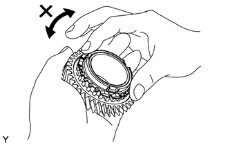
Coat the 5th gear cone with manual transmission gear oil. Check the braking effect of the No. 1 synchronizer ring. Turn the No. 1 synchronizer ring in one direction while pushing it against the 5th gear cone. Check that the ring locks.
If the braking effect is insufficient, apply a small amount of the fine lapping compound between the No. 1 synchronizer ring and 5th gear cone. Lightly rub the No. 1 synchronizer ring and 5th gear cone together.
- NOTICE:
-
Ensure the fine lapping compound is completely washed off after rubbing.
Check the braking effect of the No. 1 synchronizer ring again.
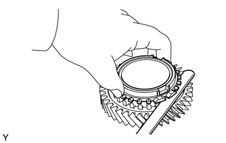
Using a feeler gauge, measure the clearance between the No. 1 synchronizer ring back and 5th gear spline end.
- Standard clearance:
0.95 to 1.35 mm (0.0374 to 0.051 in.)
- Minimum clearance:
0.95 mm (0.0374 in.)
If the clearance is less than the minimum, replace the No. 1 synchronizer ring.
33370
6.INSPECT NO. 2 SYNCHRONIZER HUB ASSEMBLY
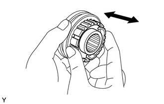
Check the sliding condition between the No. 2 hub sleeve and No. 2 clutch hub.
Check that the edges of the No. 2 hub sleeve spline gear are not worn down.
If there are any defects, replace the No. 2 synchronizer hub assembly.
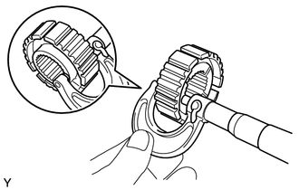
Using a micrometer, measure the thickness of the No. 2 clutch hub.
- Standard thickness:
18.52 to 18.58 mm (0.7291 to 0.7315 in.)
- Minimum thickness:
18.52 mm (0.7291 in.)
If the the thickness is less than the minimum, replace the No. 2 synchronizer hub assembly.
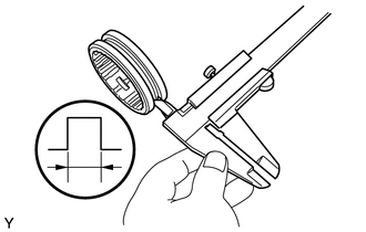
Using a vernier caliper, measure the width of the hub sleeve groove.
- Standard width:
7.05 to 7.12 mm (0.2776 to 0.2803 in.)
- Maximum width:
7.12 mm (0.2803 in.)
If the width exceeds the maximum, replace the No. 2 synchronizer hub assembly.
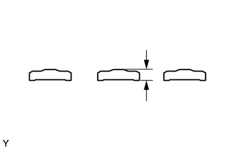
Using a vernier caliper, measure the height of the synchromesh shifting key.
- Standard height:
4.6 to 4.8 mm (0.181 to 0.189 in.)
- Minimum height:
4.6 mm (0.181 in.)
If the height is less than the minimum, replace the synchromesh shifting key.
33380
7.INSPECT NO. 3 SYNCHRONIZER HUB ASSEMBLY
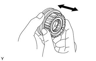
Check the sliding condition between the No. 3 hub sleeve and No. 3 clutch hub.
Check that the edges of the No. 3 hub sleeve spline gear are not worn down.
If there are any defects, replace the No. 3 synchronizer hub assembly.
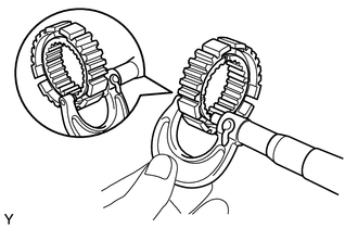
Using a micrometer, measure the thickness of the No. 3 clutch hub.
- Standard thickness:
12.1 to 12.7 mm (0.476 to 0.500 in.)
- Minimum thickness:
12.1 mm (0.476 in.)
If the thickness is less than the minimum, replace the No. 3 synchronizer hub assembly.
Using a vernier caliper, measure the width of the hub sleeve groove.
- Standard width:
7.05 to 7.12 mm (0.2776 to 0.2803 in.)
- Maximum width:
7.12 mm (0.2803 in.)
If the width exceeds the maximum, replace the No. 3 synchronizer hub assembly.
Using a vernier caliper, measure the height of the synchromesh shifting key.
- Standard height:
4.6 to 4.8 mm (0.181 to 0.189 in.)
- Minimum height:
4.6 mm (0.181 in.)
If the height is less than the minimum, replace the synchromesh shifting key.
8.INSPECT HUB SLEEVE STOPPER
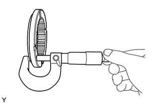
Using a micrometer, measure the thickness of the hub sleeve stopper.
- Standard thickness:
7.19 to 7.25 mm (0.2831 to 0.2854 in.)
- Minimum thickness:
7.19 mm (0.2831 in.)
If the thickness is less than the minimum, replace the hub sleeve stopper.