M5S MANUAL TRANSMISSION / TRANSAXLE INPUT SHAFT DISASSEMBLY
PROCEDURE

 33333
1.INSPECT 3RD GEAR THRUST CLEARANCE
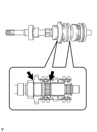
| *1 | 3rd Gear |
| *2 | 5th Gear |
Using a feeler gauge, measure the 3rd gear thrust clearance.
- Standard clearance:
0.10 to 0.52 mm (0.0039 to 0.0205 in.)
- Maximum clearance:
0.52 mm (0.0205 in.)
If the clearance exceeds the maximum, disassemble and inspect the input shaft.
33336
2.INSPECT 5TH GEAR THRUST CLEARANCE
Using a feeler gauge, measure the 5th gear thrust clearance.
- Standard clearance:
0.10 to 0.40 mm (0.0039 to 0.0158 in.)
- Maximum clearance:
0.40 mm (0.0158 in.)
If the clearance exceeds the maximum, disassemble and inspect the input shaft.
33333
3.REMOVE 3RD GEAR SUB-ASSEMBLY
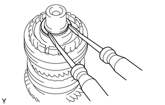
Using 2 screwdrivers and a hammer, remove the snap ring.
- NOTICE:
-
Use a piece of cloth to prevent the snap ring from flying off.
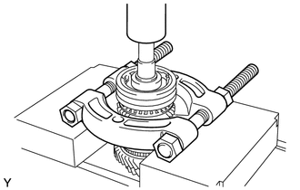
Using SST and a press, remove the No. 2 synchronizer hub assembly, No. 1 synchronizer ring and 3rd gear sub-assembly.
- SST
- 09950-00020
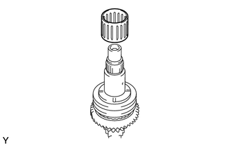
Remove the needle roller bearing.
33369B
4.REMOVE NO. 4 SYNCHRONIZER RING
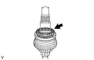
Remove the No. 4 synchronizer ring from the input shaft.
33336
5.REMOVE 5TH GEAR
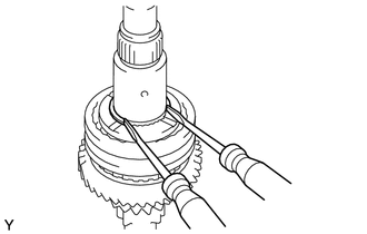
Using 2 screwdrivers and a hammer, remove the snap ring.
- NOTICE:
-
Use a piece of cloth to prevent the snap ring from flying off.
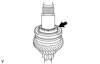
Remove the hub sleeve stopper from the input shaft.
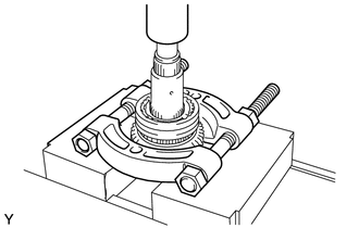
Using SST and a press, remove the No. 3 synchronizer hub assembly, No. 1 synchronizer ring and 5th gear.
- SST
- 09950-00020
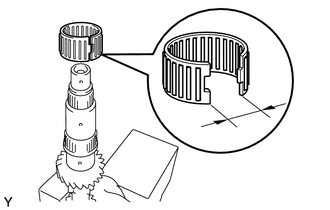
Remove the split type needle roller bearing.
- NOTICE:
-
Do not widen the opening of the split type needle roller bearing 36 mm (1.42 in.) or more.
6.REMOVE INPUT SHAFT FRONT BEARING
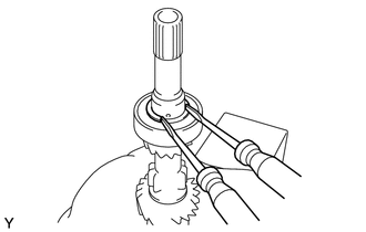
Using 2 screwdrivers and a hammer, remove the snap ring.
- NOTICE:
-
Use a piece of cloth to prevent the snap ring from flying off.
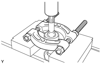
Using SST and a press, remove the input shaft front bearing.
- SST
- 09950-00020
33370
7.REMOVE NO. 2 SYNCHRONIZER HUB ASSEMBLY
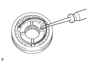
Using a screwdriver, remove the 2 synchromesh shifting key springs.
Remove the No. 2 hub sleeve and 3 synchromesh shifting keys.
33380
8.REMOVE NO. 3 SYNCHRONIZER HUB ASSEMBLY
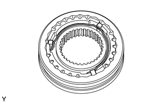
Using a screwdriver, remove the 2 synchromesh shifting key springs.
Remove the No. 3 hub sleeve and 3 synchromesh shifting keys.