DRIVE SHAFT / PROPELLER SHAFT PROPELLER SHAFT ASSEMBLY INSPECTION
PROCEDURE

 37120
1.INSPECT FRONT PROPELLER SHAFT ASSEMBLY
Check that the propeller shaft is not damaged or deformed.
If necessary, replace the front propeller shaft.
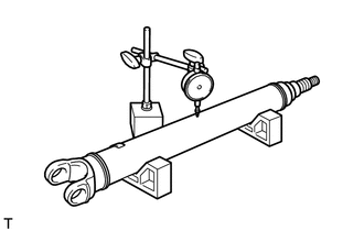
Place the propeller shaft on the V-blocks.
Using a dial indicator, check the propeller shaft runout.
- Maximum:
0.5 mm (0.020 in.)
If the shaft runout is greater than the maximum, replace the front propeller shaft.
37110
2.INSPECT REAR PROPELLER SHAFT ASSEMBLY
Check that the propeller shaft is not damaged or deformed.
If necessary, replace the rear propeller shaft.
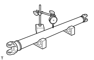
Place the propeller shaft on the V-blocks.
Using a dial indicator, check the propeller shaft runout.
- Maximum:
0.5 mm (0.020 in.)
If the shaft runout is greater than the maximum, replace the rear propeller shaft.
37230
3.INSPECT NO. 1 CENTER SUPPORT BEARING ASSEMBLY
Turn the center support bearing while applying force to it from the center in a radial direction to check for any looseness or drag as well as cracks or deformation on the bracket portion.
If necessary, replace the center support bearing.