DRIVE SHAFT / PROPELLER SHAFT PROPELLER SHAFT ASSEMBLY DISASSEMBLY
PROCEDURE

 1.INSPECT UNIVERSAL JOINT SPIDER ASSEMBLY
Check that the joints move smoothly.
Check the spider bearings for wear or damage.
Check the spider bearing axial play by turning the yoke while holding the shaft tightly.
If necessary, replace the spider bearing.
37206
2.REMOVE CENTER SUPPORT BEARING BRACKET SUB-ASSEMBLY
Remove the 2 bolts and remove the bracket from the center support bearing.
3.REMOVE UNIVERSAL JOINT SPIDER ASSEMBLY
- HINT:
-
Remove the universal joint spiders on the opposite side using the same procedure as below.
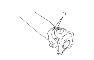
| *a | Matchmarks |
Place matchmarks on the yoke and propeller shaft.
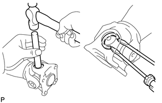
Using a brass bar and a hammer, slightly tap in the spider bearing.
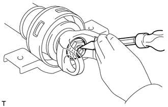
Using 2 screwdrivers, remove the 4 snap rings from the grooves.
Hold the propeller shaft in a vise between aluminium plates.
- NOTICE:
-
Do not overtighten the vise.
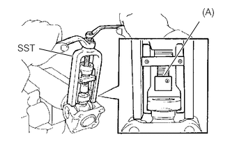
Using SST, push out the spider bearing from the propeller shaft.
- SST
- 09332-25010
- HINT:
-
Sufficiently raise the part indicated by (A) so that it does not come into contact with the spider bearing.
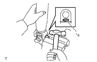
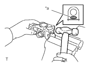
| *a | Hammering Point |
Clamp the spider bearing in a vise between aluminium plates and tap off the propeller shaft with a hammer.
- NOTICE:
- ·
Do not overtighten the vise.
·Do not tap the shaft tube.
- HINT:
-
Remove the spider bearing on the opposite side using the same procedure.
Remove the yoke with spider from the propeller shaft.
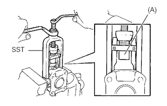
Reinstall the 2 removed spider bearings to the spider and hold the spider in a vise between aluminium plates.
- NOTICE:
-
Do not overtighten the vise.
Using SST, push out the spider bearing from the yoke.
- SST
- 09332-25010
- HINT:
-
Sufficiently raise the part indicated by (A) so that it does not come into contact with the spider bearing.
| *a | Hammering Point |
Clamp the spider bearing in a vise between aluminium plates and tap off the yoke with a hammer.
- NOTICE:
- ·
Do not overtighten the vise.
·Do not damage the yoke.
- HINT:
-
Remove the spider bearing on the opposite side using the same procedure.
Remove the universal joint spider from the yoke.
37230
4.REMOVE NO. 1 CENTER SUPPORT BEARING ASSEMBLY
Hold the propeller shaft in a vise between aluminum plates.
- NOTICE:
-
Do not overtighten the vise.
Using SST and a hammer, release the staked part of the nut.
- SST
- 09930-00010
- NOTICE:
-
Completely unstake the staked part before removing the nut.
Remove the nut.
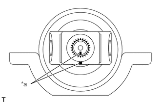
| *a | Matchmarks |
Place matchmarks on the universal joint yoke and propeller shaft.
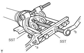
| *a | Hold |
| *b | Turn |
Using SST, remove the universal joint yoke.
- SST
- 09950-00020
09950-00030
- NOTICE:
-
Apply grease to the threads and end of the SST center bolt before use.
Remove the washer and center support bearing from the propeller shaft.