DRIVE SHAFT / PROPELLER SHAFT PROPELLER SHAFT ASSEMBLY REASSEMBLY
PROCEDURE

 37230
1.INSTALL NO. 1 CENTER SUPPORT BEARING ASSEMBLY
Hold the propeller shaft in a vise between aluminium plates.
- NOTICE:
-
Do not overtighten the vise.
Install a new center support bearing to the propeller shaft.
- NOTICE:
-
Install the center support bearing facing in the correct direction.
Install a new washer to the propeller shaft.
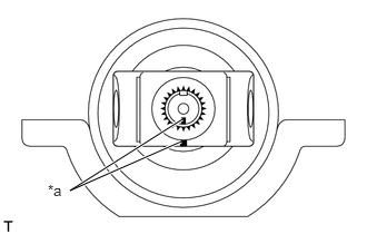
| *a | Matchmarks |
Align the matchmarks and install the universal joint yoke to the propeller shaft.
Tighten a new nut.
- Torque:
- 118 N*m (1200 kgf*cm, 87 ft.*lbf)
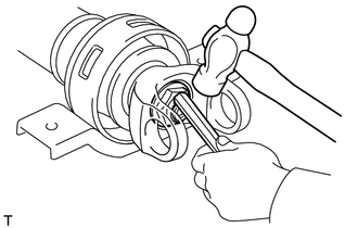
Using a chisel and hammer, stake the nut.
2.INSTALL UNIVERSAL JOINT SPIDER ASSEMBLY
- HINT:
-
Install the universal joint spiders on the opposite side using the same procedure as below.
Fit the spider into the yoke.
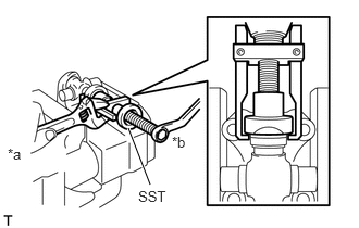
| *a | Hold |
| *b | Turn |
Hold the yoke in a vise between aluminium plates.
- NOTICE:
-
Do not overtighten the vise.
Using SST, install the 2 spider bearings to the spider.
- SST
- 09332-25010
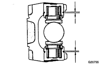
Using SST, adjust both bearings so that the snap ring grooves are at maximum and equal in width.
- SST
- 09332-25010
Install 2 new snap rings with the same thickness which will allow 0.05 mm (0.002 in.) axial play.
- Thickness of snap ring:
Part Number Thickness
mm (in.)9004B-52003 1.47 to 1.50
(0.0579 to 0.0591)9004B-52004 1.50 to 1.53
(0.0591 to 0.0602)9004B-52005 1.53 to 1.56
(0.0602 to 0.0614)9004B-52006 1.56 to 1.59
(0.0614 to 0.0626)9004B-52007 1.59 to 1.62
(0.0626 to 0.0638)9004B-52008 1.62 to 1.65
(0.0638 to 0.0650)9004B-52009 1.65 to 1.68
(0.0650 to 0.0661)9004B-52010 1.68 to 1.71
(0.0661 to 0.0673)
- NOTICE:
- ·
Use a new snap ring.
·Use snap rings as close as possible the same thickness on both sides.
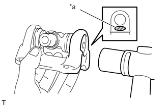
| *a | Hammering Point |
Using a hammer, tap the yoke until there is no clearance between the spider bearings and snap rings.
Align the matchmarks on the yoke and the propeller shaft.
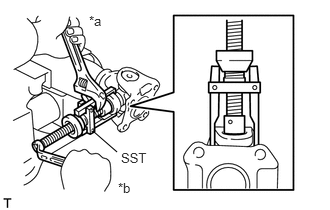
| *a | Hold |
| *b | Turn |
Hold the propeller shaft in a vise between aluminium plates.
- NOTICE:
-
Do not overtighten the vise.
Using SST, install the 2 spider bearings to the spider.
- SST
- 09332-25010
Using SST, adjust both bearings so that the snap ring grooves are at maximum and equal in width.
- SST
- 09332-25010
Install 2 new snap rings of equal thickness which will allow 0.05 mm (0.002 in.) axial play.
- Thickness of snap ring:
Part Number Thickness
mm (in.)9004B-52003 1.47 to 1.50
(0.0579 to 0.0591)9004B-52004 1.50 to 1.53
(0.0591 to 0.0602)9004B-52005 1.53 to 1.56
(0.0602 to 0.0614)9004B-52006 1.56 to 1.59
(0.0614 to 0.0626)9004B-52007 1.59 to 1.62
(0.0626 to 0.0638)9004B-52008 1.62 to 1.65
(0.0638 to 0.0650)9004B-52009 1.65 to 1.68
(0.0650 to 0.0661)9004B-52010 1.68 to 1.71
(0.0661 to 0.0673)
- NOTICE:
- ·
Use a new snap ring.
·Use snap rings as close as possible the same thickness on both sides.
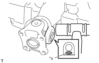
| *a | Hammering Point |
Using a hammer, tap the yoke until there is no clearance between the spider bearings and snap rings.
3.INSPECT UNIVERSAL JOINT SPIDER ASSEMBLY
Check that the joints move smoothly.
Check the spider bearing axial play by turning the yoke while holding the shaft tightly.
37206
4.INSTALL CENTER SUPPORT BEARING BRACKET SUB-ASSEMBLY
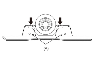
Install the bracket to the center support bearing with the 2 bolts.
- Torque:
- 37 N*m (375 kgf*cm, 27 ft.*lbf)
- NOTICE:
-
Install the bracket so that holes (A) face the front propeller shaft.